Page 47
PARTS REMOVAL AND REPLACEMENT
SEAT
3300 CE
1.
Loosen and remove the four mounting nuts and lock washers located
underneath the seat (see Figure 18).
2.
Remove the seat. Reverse the steps to reinstall.
3900 RC
The seat pads can be removed while the seat is in the seat track. Loosen and
remove the four mounting bolts from each seat pad and lift the pad free. To
remove the seat from the seat track:
1.
Loosen and remove the nyloc nut and flat washer from the rear of the
seat track. Remove the bolt (see Figure 17).
2.
Remove the seat track cover.
3.
Lift the seat adjustment handle and slide the seat to the rear and off
the track.
4.
To reinstall the seat, line up the front guide wheels with the seat
track. Carefully slide the seat forward while holding up on the seat
adjustment handle until all six wheels are in the seat track.
5.
Verify proper operation of the seat adjustment handle before
installing the seat track cover.
6.
Install the bolt through the seat track and track cover. Install and
securely tighten the flat washer and the nyloc nut.
7.
The seat track play can be adjusted by loosening the nut on both
center wheels while using a standard screwdriver to turn the bolt.
Ideally, the seat should slide easily without excessive side play.
Tighten the nuts after the wheels are adjusted (see Figure 19).
Summary of Contents for STRATUS 3300 CE
Page 1: ...Stratus Systems Owner s Manual...
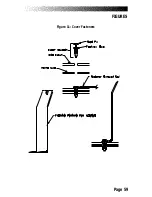
Page 66: ...Page 59 FIGURES Figure 11 Cover Fasteners...
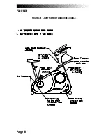
Page 67: ...Page 60 FIGURES Figure 12 Cover Fastener Locations 3300 CE...
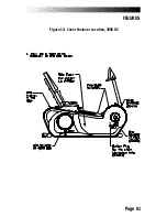
Page 68: ...Page 61 FIGURES Figure 13 Cover Fastener Location 3900 RC...
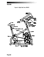
Page 69: ...Page 62 Figure 14 Right Side View 3300 CE FIGURES...
Page 70: ...Page 63 Figure 15 Left Side View 3300 CE FIGURES...
Page 71: ...Page 64 FIGURES Figure 16 Right Side View 3900 RC...
Page 72: ...Page 65 FIGURES Figure 17 Left Side View 3900 RC...
Page 73: ...Page 66 FIGURES Figure 18 Seat Adjustment Pin Assembly 3300 CE...
Page 74: ...Page 67 FIGURES Figure 19 Seat Assembly 3900 RC...
Page 75: ...Page 68 FIGURES Figure 20 Drive Chain Tension...
Page 76: ...Page 69 FIGURES Figure 21 Intermediate Shaft Assembly...
Page 77: ...Page 70 FIGURES Figure 22 J Bolt Assembly...
Page 78: ...Page 71 FIGURES Figure 23 Crank Assembly...
Page 79: ...Page 72 FIGURES Figure 24 Alternator Flywheel Assembly...

