Page 29
STRATUS SYSTEMS CONSOLE
5.
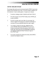
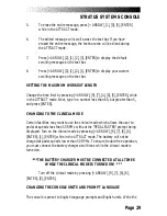
To erase the entire message, press [+ ARROW], [1], [0], [5], [ENTER]
while in the ATTRACT mode.
6.
The edited message will scroll across the text bar. If you have
erased the entire message, the text bar area will be blank during
the ATTRACT mode.
7.
Press [+ ARROW], [2], [1], [2], [3], [ENTER] to display the default
scrolling message on the text bar.
8.
Press [+ ARROW], [2], [1], [2], [1], [ENTER] to display your custom
scrolling message on the text bar.
SETTING THE MAXIMUM WORKOUT LENGTH
Change the time limit by pressing [+ ARROW], [9], [7], [4], [0], [5], [ENTER], while
in the ATTRACT mode. Next, type in a number less than 60, but greater than 5,
and press [ENTER].
CHANGING TO THE CLINICAL MODE
Certain facilities may want to use the clinical mode which allows the user to
pedal at speeds less than 50 RPMs without the "PEDAL FASTER" prompt being
displayed. Turn on the clinical mode by pressing [+ ARROW], [9], [7], [6], [6],
[ENTER], [1], [ENTER] while in the ATTRACT mode. The battery will not be
charged at pedal speeds lower than 50 RPMs. To ensure trouble-free operation,
you must connect the battery charger at all times while the clinical mode is
turned on.
*** THE BATTERY CHARGER MUST BE CONNECTED AT ALL TIMES
WHILE THE CLINICAL MODE IS TURNED ON!
***
Turn off the clinical mode by pressing [+ ARROW], [9], [7], [6], [6],
[ENTER], [0], [ENTER].
CHANGING THE CONSOLE UNITS AND PROMPT LANGUAGE
The console is preset to English language prompts and English units. While the
Summary of Contents for STRATUS 3300 CE
Page 1: ...Stratus Systems Owner s Manual...
Page 66: ...Page 59 FIGURES Figure 11 Cover Fasteners...
Page 67: ...Page 60 FIGURES Figure 12 Cover Fastener Locations 3300 CE...
Page 68: ...Page 61 FIGURES Figure 13 Cover Fastener Location 3900 RC...
Page 69: ...Page 62 Figure 14 Right Side View 3300 CE FIGURES...
Page 70: ...Page 63 Figure 15 Left Side View 3300 CE FIGURES...
Page 71: ...Page 64 FIGURES Figure 16 Right Side View 3900 RC...
Page 72: ...Page 65 FIGURES Figure 17 Left Side View 3900 RC...
Page 73: ...Page 66 FIGURES Figure 18 Seat Adjustment Pin Assembly 3300 CE...
Page 74: ...Page 67 FIGURES Figure 19 Seat Assembly 3900 RC...
Page 75: ...Page 68 FIGURES Figure 20 Drive Chain Tension...
Page 76: ...Page 69 FIGURES Figure 21 Intermediate Shaft Assembly...
Page 77: ...Page 70 FIGURES Figure 22 J Bolt Assembly...
Page 78: ...Page 71 FIGURES Figure 23 Crank Assembly...
Page 79: ...Page 72 FIGURES Figure 24 Alternator Flywheel Assembly...

