


DLS 400E3 Operating Manual
Spirent Communications - Page
4-11
7104000537 03/04 -2
bit 5: ESB (Event Status Bit)
It indicates that at least one bit of the Event Status Register is non zero and enabled. If
ESB goes high and is enabled then MSS goes high.
bit 6: MSS/RQS (Master Summary Status/Request Service)
MSS is raised when either MAV or ESB are raised and enabled. When the status of MSS
changes, the whole Status Byte Register is copied into the Status Byte of the GPIB con-
troller, where bit 6 is called RQS. When RQS goes high so does the SRQ line, and in
response to an IEEE 488.1 Serial Poll command, both are cleared.
RQS and SRQ are defined by the IEEE 488.1 standard and are hardware related. MSS
summarizes all the status bits of the DLS 400E3, as defined by the IEEE 488.2 standard.
bits 7, 3, 2, 1,and 0: these bits are not used by the host system.
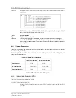
4.8.1.1 Event Status Register (ESR)
The Event Status Register monitors events within the system and reports on those enabled. It records transi-
tory events as well. The host system implements only the IEEE 488.2 Standard Event Status Register (ESR).
It is defined as:
bit 0
Operation Complete. This bit is set in response to the *OPC command when the current operation
is complete.
bit 1
Request Control. The host system does not have the ability to control the IEEE bus, and so this bit
is always 0.
bit 2
Query Error. There was an attempt to read an empty output queue or there was an output queue
overflow. (maximum output queue capacity is 75 bytes).
bit 3
Device Dependent Error. This error bit is set when the host system receive a command to set the
length of a fixed loop. Only variable loops can have their length changed.
bit 4
Execution Error. The data associated with a command was out of range.
bit 5
Command Error. Either a syntax error (order of command words) or a semantic error (spelling of
command words) has occurred. A GET (Group Execute Trigger) or *TRG command also sets this
bit.
bit 6
User Request. Indicates that you have activated a Device Defined control through the front panel.
Not used, so this bit is always 0.
bit 7
Power on. This bit is set when the host system is turn on. Sending *ESR? clears the bit and stays
clear until the power is turned on again.
The setting of the Event Status Register can be read with the Event Status Register query command
(*ESR?). This puts the value of the register in the output queue, AND clears the register.
4.8.2
Host System Synchronization
The program controlling the host system can use three different commands to synchronize with the DLS
400E3: *OPC, *OPC? and *WAI. Following are the main differences:
Summary of Contents for DLS 400E3
Page 1: ...Operating Manual DLS 400E3 ADSL European Wireline Simulator Revision 2 March 2004...
Page 2: ......
Page 10: ...DLS 400E3 Operating Manual Page 1 6 Spirent Communications 7104000537 03 04 2...
Page 52: ...DLS 400E3 Operating Manual Page 7 2 Spirent Communications 7104000537 03 04 2...
Page 56: ...DLS 400E3 Operating Manual Page 9 2 Spirent Communications 7104000537 03 04 2...
Page 58: ...DLS 400E3 Operating Manual Page 10 2 Spirent Communications 7104000537 03 04 2...
Page 64: ...DLS 400E3 Operating Manual Page 12 4 Spirent Communications 7104000537 03 04 2...


