


DLS 400E3 Operating Manual
Page 3-2 - Spirent Communications
7104000537 03/04 -2
3.3
Accessing the Main Window
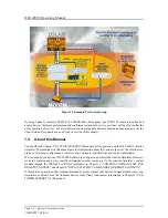
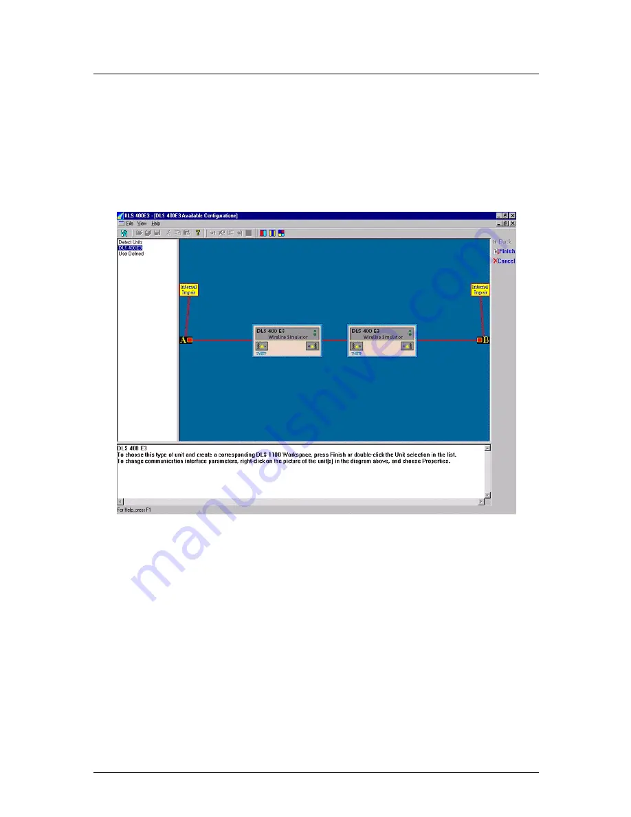
The left-hand side of main window displays a supported equipment menu listing all available models of sim-
ulators you can configure. When you highlight any item in the menu a diagram of the selected system
appears on the right-hand side of the main window workspace.
To access the main window:
1) From
the
Start
menu, select DLS 400E3 Software or double-click the icon on your desktop. The
DLS 400E3 - (DLS 400E3 Available Configurations)
window appears.
Figure 3.1 DLS 400E3 Software - Main Window
3.4
Accessing the Control Window (s)
The DLS 400E3 control window (s) contains the following in the workspace area as shown in Figure 3.2:
•
Loop Display window that displays which test loop (s) is currently configured for the DLS 400E3.
•
Unit Configuration window that displays the Unit 1 and 2 addresses and settings for the selected test
loop.
•
Micro-interrupt window that allows you to set the micro-interruption feature.
•
Optionally, Side A and Side B windows that allow you to set internal noise injector card configurations.
Summary of Contents for DLS 400E3
Page 1: ...Operating Manual DLS 400E3 ADSL European Wireline Simulator Revision 2 March 2004...
Page 2: ......
Page 10: ...DLS 400E3 Operating Manual Page 1 6 Spirent Communications 7104000537 03 04 2...
Page 52: ...DLS 400E3 Operating Manual Page 7 2 Spirent Communications 7104000537 03 04 2...
Page 56: ...DLS 400E3 Operating Manual Page 9 2 Spirent Communications 7104000537 03 04 2...
Page 58: ...DLS 400E3 Operating Manual Page 10 2 Spirent Communications 7104000537 03 04 2...
Page 64: ...DLS 400E3 Operating Manual Page 12 4 Spirent Communications 7104000537 03 04 2...