


DLS 400E3 Operating Manual
Page 2-4 - Spirent Communications
7104000537 03/04 -2
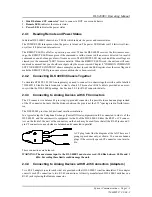
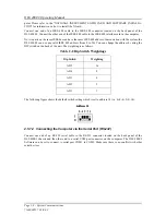
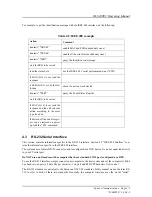
The pin out of the RJ-45 female connector is shown in Figure 2.2.
Wiring
Figure 2.2 RJ-45 Female Connector
In Figure 2.2 "RJ-45 Female Connector", Pins 4 (Tip) and 5 (Ring) of the RJ-45 connectors, the center 2
pins, carry the signal.
Note:
RJ-11 male connectors can also mate to RJ-45 female receptacles.
These connections are balanced.
WARNING: The maximum input to the DLS 400E3 must not exceed -30 dBm between 50 Hz and 1
kHz. Exceeding these limits could damage the unit.
2.5
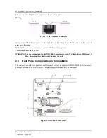
Back Panel Components and Connections
The connections on the rear panel are used for remote control (computer with DLS 400E3 Software), exter-
nal noise injection and power. Figure 2.3 displays the key components of the rear panel.
Figure 2.3 DLS 400E3 Back Panel
Summary of Contents for DLS 400E3
Page 1: ...Operating Manual DLS 400E3 ADSL European Wireline Simulator Revision 2 March 2004...
Page 2: ......
Page 10: ...DLS 400E3 Operating Manual Page 1 6 Spirent Communications 7104000537 03 04 2...
Page 52: ...DLS 400E3 Operating Manual Page 7 2 Spirent Communications 7104000537 03 04 2...
Page 56: ...DLS 400E3 Operating Manual Page 9 2 Spirent Communications 7104000537 03 04 2...
Page 58: ...DLS 400E3 Operating Manual Page 10 2 Spirent Communications 7104000537 03 04 2...
Page 64: ...DLS 400E3 Operating Manual Page 12 4 Spirent Communications 7104000537 03 04 2...


