


DLS 400E3 Operating Manual
Spirent Communications - Page
2-3
7104000537 03/04 -2
4.
Side B balanced CF connector
1:
used to connect a DUT or a second chassis
5.
Remote LED:
indicates the remote status
6.
Power LED
: indicates the power status
2.4.1
Reading Remote and Power Status
Individual DLS 400E3 chassis have 2 LEDs which indicate the power and remote status.
The POWER LED turns green when the power is turned on. The power LED blinks red if it fails its self-test,
or yellow if it detects an internal error.
The REMOTE LED is off after a power-up or a reset. When the DLS 400E3 receives the first remote mes-
sage, the REMOTE LED turns green if the command is valid or turns red if an error is detected. An invalid
command or an out-of-range value will cause an error. The REMOTE LED stays red until the error flags are
cleared (see the command *ESR? for more details). When the REMOTE LED is red, the unit can still com-
municate as normal, but you should investigate why the error occurred. Chapter 4 "COMMON COMMAND
SET FOR REMOTE CONTROL" shows examples on how to read the ESR register, clear the error flags and
make the REMOTE LED green once error conditions have been resolved.
2.4.2
Connecting DLS 400E3 Chassis Together
To simulate ETSI TS 101 388 line segments you need to connect two chassis together with a cable labelled
7102040514. Side B of unit 1connects to side A of unit 2. This one foot RJ-45 cable is provided as an acces-
sory within the DLS 400E3 package. See Section 2.4.4 for RJ-45 connector details.
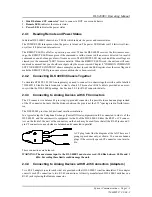
2.4.3
Connecting to Analog Devices with CF Connectors
The CF connector is a balanced 3-pin (ring, tip, ground) connector. It is possible to use banana plugs instead
of the CF connector, but note that the distance between the pins is not the 0.75" spacing used in North Amer-
ica.
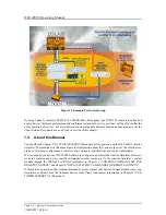
The DLS 400E3 provides bi-directional wireline simulation.
In a typical setup the Telephone Exchange (Central Office) equipment would be connected to side A of the
DLS 400E3, and the customer site equipment to side B of the DLS 400E3. Either the RJ-45 or CF connec-
tors on the front of the unit, or the connectors on the back may be used. Note that all the RJ-45 jacks and 3-
pin CF connectors on each side are balanced and connected in parallel.
A CF plug looks like the diagram at the left. There are 3
prongs spaced unevenly, as shown. You can use banana
plugs if the correctly spaced CF connector is not availa-
ble.
These connections are balanced.
WARNING: The maximum input to the DLS 400E3 must not exceed -30 dBm between 50 Hz and 1
kHz. Exceeding these limits could damage the unit.
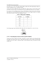
2.4.4
Connecting to Analog Devices with RJ-45 Connectors (Adapters)
Two RJ–45 adapters (one for each side) are provided with all DLS 400E3 wireline simulators. This adapter
converts each CF connection to two RJ–45 connections. All newly manufactured DLS 400E3 units have an
RJ-45 jack replacing the Bantam connector.
Summary of Contents for DLS 400E3
Page 1: ...Operating Manual DLS 400E3 ADSL European Wireline Simulator Revision 2 March 2004...
Page 2: ......
Page 10: ...DLS 400E3 Operating Manual Page 1 6 Spirent Communications 7104000537 03 04 2...
Page 52: ...DLS 400E3 Operating Manual Page 7 2 Spirent Communications 7104000537 03 04 2...
Page 56: ...DLS 400E3 Operating Manual Page 9 2 Spirent Communications 7104000537 03 04 2...
Page 58: ...DLS 400E3 Operating Manual Page 10 2 Spirent Communications 7104000537 03 04 2...
Page 64: ...DLS 400E3 Operating Manual Page 12 4 Spirent Communications 7104000537 03 04 2...


