© 2009 SpinetiX S.A. All rights reserved.
10
INSTALLING HMP100
Installing HMP100 is a relatively simple task.
Integrators and electricians appreciate the limited number of cables required to connect
the HMP100 unit and its light form factor: a Velcro stripe can be used secure HMP100 in
any position you like.
Since the unit does not heat and does not contain mechanical parts, it can be installed
indoor almost everywhere: just be careful of water and humidity infiltrations!
Once installed, getting started with HMP100 is a matter of few steps. In the following
sections we show how to connect one or more units onto your network and how to
publish content from the Hyper Media Director software to specific displays.
Learn HMP100 connectors
HMP100 exposes several I/O connectors identified by small icons. In this guide we will
only use those required to test that your HMP100 unit is functional.
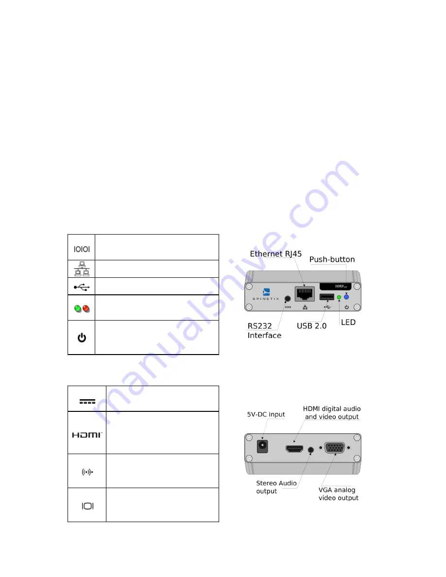
HMP100 Front panel connectors
RS232 interface: the serial port
is used in development mode
only
Ethernet RJ45: plug the Ethernet
cable in this socket
USB 2.0 supports an USB
memory device
LEDs The green/red LED gives an
indication on the state of the
system.
Push-button: this push-button is
used to manually reboot the
HMP100 unit. Keep it pressed fro
few seconds.
HMP100 Back panel connectors
5V-DC input: power socket
where the power adapter DC
output jack is to be plugged.
Digital Video out. Standard
High Definition Media
Interface (HDMI) available on
most recent digital displays. It
also carries digital audio.
Analog Audio out: This stereo
audio output can be used to
drive amplified audio
speakers.
Analog Video out: Standard
Video Graphics Array (VGA)
supported by most LCD
screens.


