background image

41

SPEKTRUM DX18t • TRANSMITTER INSTRUCTION MANUAL

EN

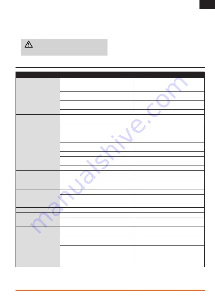
TROUBlESHOOTING GUIDE

Problem

Possible Cause

Solution

Aircraft will not Bind (during  
binding) to transmitter

Transmitter too near aircraft during binding process

Move powered transmitter a few feet fromthe aircraft, 
disconnect and reconnect the flight battery to the 
aircraft

Aircraft or transmitter is too close to large metal object

Move the aircraft or transmitter away from the large 
metal object

The bind plug is not installed correctly in the bind port

Install bind plug in bind port and bind the aircraft to the 
transmitter

Flight battery/Transmitter battery charge is too low

Replace/recharge batteries

Aircraft will not link (after binding) 
to transmitter

Transmitter too near aircraft during linking process

Move powered transmitter a few feet from aircraft, 
disconnect and reconnect flight battery to aircraft

Aircraft or transmitter is too close to large metal object

Move the aircraft or transmitter away from the large 
metal object

Bind plug left installed in bind port

Rebind transmitter to the aircraft and remove the bind 
plug before cycling power

Aircraft bound to different model memory  
(ModelMatch™ radios only)

Select correct model memory on transmitter

Flight battery/Transmitter battery charge is too low

Replace/recharge batteries  

Transmitter may have been bound using different DSM 
protocol

Bind aircraft to transmitter

Damaged remote receiver or receiver extension

Required remote receiver is not connected

The receiver goes into failsafe 
mode a short distance away  
from the transmitter

Check the receiver antenna to be sure it is not cut or 
damaged

Replace or contact Horizon Product Support

Main and remote receivers too near each other

Install main and remote receivers at least 2 inches 
(51mm) apart

Receiver quits  
responding during operation

Low battery voltage

Completely recharge flight battery

Loose or damaged wires or connectors between battery 
and receiver

Do a check of the wires and connection between 
battery and receiver. Repair or replace wires and/or 
connectors

Receiver loses its bind

Bind button pressed before transmitter powered on

Rebind by performing binding instructions

Receiver slowly blinking at  
landing (DSM2 Only)

Loss of power to the receiver during flight

Check battery voltage

System powered on and connected, then receiver pow-
ered off without powering off transmitter

Power off transmitter when receiver is powered off

Flight log registers undesirable 
number of fades, losses or holds 
or aircraft responds irregularly to 
controls 

Poor signal reception

Reposition remote receivers for improved RF signal 
path diversity

Electronic feedback

Check for and stop feedback from servos or motor 
systems to the ESC or receiver

Low power

Check aircraft power draw and increase battery power 
or decrease power demand by installed systems. 
Ensure all aircraft batteries are fully charged. Ensure 
the installed BEC for an electric aircraft is adequate for 
the power demand

5.  Remove and keep 2 screws from the installed throttle ratchet 

strip. 

6.  Do not remove grease from plastic part under the strip.
7.  Attach the strip to the gimbal using the 2 screws. 
8.  Tighten the spring tension screw to get desired stick tension. 

CAUTION:

 Make sure no wires or components  

are pinched or damaged while installing the back cover.

9.  Carefully close the transmitter case using the 4 screws and 

re-install the hand grips. 

10. Connect the battery to your transmitter.

Summary of Contents for DX18t

Page 1: ...Instruction Manual Bedienungsanleitung Manuel d utilisation Manuale di Istruzioni 18t 18 ...

Page 2: ...When working with a model always power on the transmitter first and power off the transmitter last After a model is bound to a transmitter and the model is set up in the transmitter always bind the model to the transmitter again to establish failsafe settings Pilot Safety Always make sure all batteries are fully charged before flying Time flights so you can fly safely within the time allotted by y...

Page 3: ...ownload the latest AirWare firmware updates A registration reminder screen occasionally appears until you register your transmitter When you register your transmitter the reminder screen does not appear again Box Contents DX18t Transmitter 2500mAh Li Po Transmitter Pack Installed in transmitter SPM6803 Male Female Bind plug Global Power Supply SD card Recommended operating temperature 32 131 F ...

Page 4: ...26 Throttle Curve 26 AS3X Gains 27 Mixing 27 Sequencer 28 Range Test 29 Timer 30 Telemetry 30 Custom Voice Setup 30 System Setup 31 Monitor 31 X Plus Monitor 31 ACRO Airplane 32 Aircraft Type 32 Recommended Servo Connections 32 Elevon Servo Control 33 Flap System 33 ACRO Mixing 33 Acro Gyro Function 34 Pitch Curve Function 34 HELI Helicopter 35 Heli Model Type 35 Swash Type 35 Pitch Curve 35 Swash...

Page 5: ...mitter Batteries The DX18t has an internal charger designed to charge the included 2 cell Li Po battery at a charge rate of 200mAh The charge port is not polarity dependent NOTICE Never connect an external battery charger to your DX18t transmitter If you wish to charge the Li Po battery using a Li Po charger you must remove the battery from the transmitter before charging The first time you charge...

Page 6: ...rim Mode 1 G Aileron Trim H SD Card Slot I Belt Release Button J Scroll wheel K Programmable Slider P2 Function L Speaker Grille M Screen N Programmable Slider P1 O Charge Port P On Off Switch Q Rudder Trim R Throttle Trim Mode 2 Elevator Trim Mode 1 S Throttle Rudder Stick Mode 2 Elevator Rudder Stick Mode 1 T L Module Tension U Trainer Port On back of transmitter V Headphone Port On back of tran...

Page 7: ...ge the mode in System Settings under the System Setup menu Screw in the star shaped screw until you are not able to turn or when the cantilever arm has fully disengaged Adjust the tension screws to your preference Mode Change 2 4 Throttle Strap Tension Mode Change 1 3 Mode Change 2 4 Elevator Tension 2 Elevator Tension 1 Aile Rudd Tension 2 1 Aile Rudd Tension 1 2 Trainer Port under antenna Audio ...

Page 8: ... scroll wheel to view the servo monitor The Main Screen appears when you power on the transmitter Press the scroll wheel once to display the Function List When you want to change a value in a screen for a particular control direction move the control in the desired direction Turn Press Press Press Enter Choose or Exit Turn Move between options or change value in an option Hold Hold for 3 seconds a...

Page 9: ...ht Bind then press the scroll wheel Binding is complete when the lights in the receivers are solid orange 6 Power off the receiver and remove the bind plug 1 Lower throttle to the lowest position and make sure the transmitter is powered off 2 Insert the bind plug into the BIND DATA port 3 Insert the ESC plug into the THRO port 4 Connect battery to ESC and turn on the ESC switch if available The LE...

Page 10: ...mand The Hold Last Command failsafe maintains the last command on all channels except throttle If the radio signal is lost the aircraft maintains the commanded heading until the receiver regains signal To program Hold Last Command follow the provided binding instructions in this instruction manual To Test Hold Last Command 1 Power on the transmitter and receiver 2 Move one of the control sticks to...

Page 11: ...ution of 512 and variable latency from 22ms to about 88ms When X Plus is active the first 10 channels default to 22ms SD Card Installing the SD Card The included SD Card enables you to Import copy models from another DX18t transmitter Export transfer models to another DX18t transmitter Update AirWare software and sound files in the transmitter To install the SD Card 1 Power off the transmitter 2 O...

Page 12: ...uencer Range Test Timer Telemetry Custom Voice Setup System Setup Monitor XPlus Monitor System Setup List Model Select Model Type Model Name Swashplate Type F Mode Setup Spoken Flight Mode Channel Assign Trim Setup Model Utilities Warnings Telemetry Preflight Setup Frame Rate Bind Trainer Analog Switch Setup System Settings Model Utilities Transfer SD Card Function List Servo Setup D R and Expo Th...

Page 13: ...lecting the model type To change the model type 1 Scroll to the desired model type and press the scroll wheel The Confirm Model Type screen appears 2 Select Yes and press the scroll wheel to confirm the model type All data will be reset Selecting No will exit the Confirm Model Type screen and return to the Model Type screen Model Name Model Name enables you to assign a custom name to the current m...

Page 14: ...nel Assign Spoken Flight Mode Setup Enables you to assign custom names to the Flight Mode positions Flight Mode names can include up to 20 characters including spaces To change the Flight Mode name 1 Scroll to the Flight Mode name you wish to change and press the scroll wheel 2 Scroll to the character position you wish to change and press the scroll wheel once A flashing box appears 3 Scroll left ...

Page 15: ...rim step value and scroll left or right to change the value 3 Press the scroll wheel to save the selection Trim Type The two Trim Type options are Common and F Mode Common trim type maintains the same trim values for all flight modes F Mode trim type enables you to save trim values for individual flight modes if you find for example the aircraft requires aileron trim in Flight Mode 1 but not in Fl...

Page 16: ...nfirm Selecting Cancel will return to the System Setup screen 5 Select the To model as the current model then bind the transmitter and receiver Copying a model does not copy the bind from the original model You cannot use the Model Copy screen to copy model programming to an SD Card To copy model programming to the SD Card please see Transfer SD Card Model Utilities In the Model Utilities function...

Page 17: ...t then select Auto Config Configuring flashes for 5 seconds and any new sensors appear in the list 4 Adjust the sensor alert values as necessary Status Reports Status Reports determines how often the transmitter refreshes the data on the screen Each telemetry sensor can be adjusted independently For example the RPM status report can refresh every 10 seconds while the altimeter sensor refreshes eve...

Page 18: ...d modulation mode Select the option you wish to change and press the scroll wheel You must use digital servos if you select 11ms frame rate Analog and digital servos can be used with a 22ms frame rate Modulation Mode We recommend using DSMX default modulation mode When DSMX is active the transmitter operates in DSMX with DSMX receivers and DSM2 with DSM2 receivers The transmitter automatically det...

Page 19: ...itter to the model 2 Connect the trainer cord SPM6805 to the back of the master transmitter 3 Make sure the master and slave transmitter battery packs are fully charged 4 Make sure the slave transmitter is powered off The slave transmitter receives power when you connect the trainer cord 5 Connect the trainer cord to the slave transmitter 6 The slave transmitter screen displays information but doe...

Page 20: ...ng the instructions provided with that transmitter 7 After a successful bind the following screen should appear 8 Move the trainer switch on the master transmitter to transfer model control from the master to the slave 9 Release the trainer switch and the master transmitter regains control of the model Master Override The Master Override feature enables the instructor to immediately regain control...

Page 21: ...wheel to save the selection 3 Select NEXT in the lower left corner until the Calibration screen appears 4 Move all transmitter controls to the center position and complete the calibration process before exiting the System Settings menu See Calibrating Your Transmitter for more information Battery Alarm Battery Alarm enables you to change the transmitter battery type and the alarm voltage limit The...

Page 22: ...ity and the Low Voltage warnings Serial Number The Serial Number screen displays the transmitter serial number and AirWare software version Reference the Serial Number screen any time you need to register your transmitter or update the AirWare software from the Spektrum Community website Exporting the Serial Number to the SD Card You may find it helpful to export the transmitter serial number to a...

Page 23: ...must show DSM2 or DSMX in the upper left corner Export Model You can use the Export Model option to export a single model file to the SD Card 1 Make sure the active model file is the one you wish to Export 2 Scroll to Select Option and press the scroll button once 3 Scroll to Export Model and press the scroll button again to save the selection The Export to SD screen appears The first three charac...

Page 24: ...o Setup menu contains the following functions Travel Adjust Sub Trim Reverse Speed Abs Absolute Travel Balance Travel Adjust Travel Adjust sets the overall travel or endpoints of the servo arm movement To adjust travel values 1 Scroll to the channel you wish to adjust and press the scroll wheel When adjusting travel values assigned to a control stick a Center the control stick to adjust both direc...

Page 25: ...wheel once Scroll left or right to select the channel you wish to change and press the scroll wheel again to save the selection 2 Scroll to dual rate and press the scroll wheel Scroll left or right to change the value and press the scroll wheel again to save the selection Exponential affects control response sensitivity around center but has no affect on overall travel Positive exponential decreas...

Page 26: ...e V Tail Differential menu option only appears when V Tail A or V Tail B is active in Aircraft Type To adjust the V Tail Differential 1 Scroll to Switch and press the scroll wheel Scroll right to select On Differential is always on or assign the differential to a switch position 2 Press the scroll wheel a second time to save the selection 3 Scroll to Diff and press the scroll wheel once to change ...

Page 27: ...tch must be in the active position Assigning a Mix to a Switch If you wish to assign a mix to a switch position 1 Scroll to Switch and press the scroll wheel 2 Scroll left or right to the switch you wish to use and press the scroll wheel to save the selection 3 Scroll to the switch position where you want the mix to be active The mix is Active when the box is filled and Inactive when the box is op...

Page 28: ...erent sequences S1 through S5 are available to control 2 functions each A and B in 2 timing directions forward or reverse Sequences appear throughout function screens as assignable switches CAUTION Always review the action of a sequence on the Monitor or X Plus Monitor screen BEFORE operating the model to ensure controls act as desired Failure to do so could cause a crash resulting in property dam...

Page 29: ...the power output This allows for a range test to confirm the RF link is operating correctly Perform a range check at the beginning of each flying session to confirm system operation To Access the Range Test screen 1 With the transmitter on and the main or telemetry screen displayed press the scroll wheel The Function list is displayed 2 Scroll to Range Test then press the scroll wheel to access th...

Page 30: ... so you can access the telemetry functions from either list You must power off the receiver and transmitter then power them both on to reset the telemetry data You can reset min max values by pressing the CLEAR button NEVER change Telemetry settings when the aircraft is powered on There is a brief interruption in RF output when exiting the Telemetry screen and may cause a Hold condition Use the cu...

Page 31: ...n screen will appear that warns that RF will be disabled the transmitter will no longer transmit Press YES if you are sure and want to access the System List If you are not sure press NO to exit to the main screen and continue operation If you do not press YES or NO the system will exit to the main screen and continue operation within approximately 10 seconds WARNING Do not press YES unless the mo...

Page 32: ...of either of these activates the V Tail Differential menu option Both Canard Types are available in the Tail Type listing with Elevon A or Elevon B selected Activates the Gyro menu option in the Function List Activates Pitch in the Function List If Pitch Curve is active only one gyro will be available Select wing and tail types before doing any other programming ACRO Airplane Image Selection Press...

Page 33: ...lever you wish to use to control the flap channel 5 Assign the Flap travel values and any desired Elevator mixing 6 Select a Flap speed if desired Norm default does not have a delay Flap speed options range from 0 1s to 30 seconds ACRO Mixing Rudder to Aileron Elevator Rudder to Aileron Elevator mixing corrects coupling in knife edge flight Add Elevator mixing if the aircraft pitches toward the la...

Page 34: ... For example if the gyro is installed to assist on the ailerons select Ail b Select the second Inh and assign the output channel for the Gyro for example the Gear channel 5 Select the Curve you wish to edit 6 Add the desired gyro gain values to the points on the curve 7 Assign the switch positions to activate the gyro curve The curve is active when the box is solid Pitch Curve Function In Acro mod...

Page 35: ... mix values as needed for correct direction response of the helicopter Before making adjustments to the Swashplate mix make sure the throttle collective pitch input moves the entire swashplate up or down If the servos are not moving in the same direction reverse them as necessary in the Servo Setup menu option When the entire swashplate moves up or down 1 Adjust the mix value for the Aileron and E...

Page 36: ...e Gyro must be on different channels We recommend using AUX2 for the Governor output channel 5 Select a switch to control the Governor 6 Press the BACK button to save the selections and return to the Function List The Tail Curve function mixes tail rotor input with the throttle collective function to counter torque from the main rotor blades when using a non heading hold tail lock gyro or when usi...

Page 37: ...to your sailplane manual for recommended control throws CAUTION Always do a Control Test of your model with the transmitter after programming changes to make sure your model responds as desired Camber System Camber Preset is only available when 2 or 4 aileron wing type is selected in Sailplane Type The Camber Preset function enables you to program the ailerons flaps wing tips and elevator for a sp...

Page 38: ...ns Elevator to Flap Elevator to Flap mix creates additional lift allowing a tighter turn The entire trailing edge of the wing aileron and flap operate as flaps camber increase when you apply elevator An offset is provided which is typically used for Snap Flaps With Snap Flap no Elevator to Flap mix occurs until the offset value is reached Typically this offset is at 70 up elevator so that beyond 7...

Page 39: ... components that cause a receiver to have too little power supply include Receiver battery number of cells capacity cell type state of charge Switch harness Battery leads Regulator where used Power bus where used A Spektrum receiver s minimum operational voltage is 3 5 volts This battery charge capacity compensates for discharge during flight or for flight loads larger than ground test loads CAUTI...

Page 40: ...nect the battery from your transmitter 2 Carefully pull up the top of the left and right rear hand grips on the back of the transmitter to expose the 2 case screws Tip Only the top portion of the grip needs to be pulled back the entire grip does not need to be removed to access the case screws 3 Carefully remove and keep 4 screws from the back of the transmitter 2 in lower corners and 2 under the ...

Page 41: ... damaged Replace or contact Horizon Product Support Main and remote receivers too near each other Install main and remote receivers at least 2 inches 51mm apart Receiver quits responding during operation Low battery voltage Completely recharge flight battery Loose or damaged wires or connectors between battery and receiver Do a check of the wires and connection between battery and receiver Repair ...

Page 42: ...ange or modify this warranty at any time without notice WARRANTY SERVICES Questions Assistance and Services Your local hobby store and or place of purchase cannot provide warranty support or service Once assembly setup or use of the product has been started you must contact your local distributor or Horizon directly This will enable Horizon to better answer your questions and service you in the ev...

Page 43: ...ell as Visa MasterCard American Express and Discover cards By submitting any item to Horizon for service you are agreeing to Horizon s Terms and Conditions found on our website http www horizonhobby com content _service center_ render service center ATTENTION Horizon service is limited to Product compliant in the country of use and ownership If received a non compliant product will not be serviced...

Page 44: ...ed events air shows or model demonstrations unless a The aircraft control system and pilot skills have success fully demonstrated all maneuvers intended or anticipated prior to the specific event b An inexperienced pilot is assisted by an experienced pilot 4 When and where required by rule helmets must be properly worn and fastened They must be OSHA DOT ANSI SNELL or NOCSAE approved or comply with...

Page 45: ...xecutive Vice President Product Divisions Horizon Hobby LLC Instructions for disposal of WEEE by users in the European Union This product must not be disposed of with other waste Instead it is the user s responsibility to dispose of their waste equipment by handing it over to a designated collections point for the recy cling of waste electrical and electronic equipment The separate collection and ...

Page 46: ...marks or registered trademarks of Horizon Hobby LLC The Spektrum trademark is used with permission of Bachmann Industries Inc Futaba is a registered trademark of Futaba Denshi Kogyo Kabushiki Kaisha Corporation of Japan The SD Logo is a trademark of SD 3C LLC All other trademarks service marks and logos are property of their respective owners US 7 391 320 Other patents pending 44019 Created 07 201...

Reviews: