background image


51 

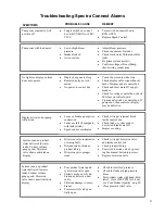
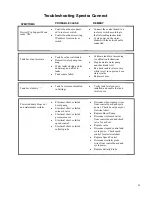
Pump runs constantly, will 
not turn off 



Turn switch on control box to 
RUN AUTO 



Replace Speed Control 



Toggle switch on control 
box to RUN MAN or SER-
VICE 

Display activates, but pump 
will not run 



Loose or broken pump wire 
connection 



Tanks are full (if equipped 
with tank switch) 



Speed control overheated 



Check wiring at terminal block 
inside control box 



Check tanks– system cannot 
be started if tanks are full. 



Improve cooling 

System runs, no product 
water delivered to water 
tanks, Product volume 
gauge good, Diversion 
valve shows deactivated on 
display 



Poor product water quali-
ty diversion valve open 



Salinity probe out of cali-
bration or defective, bad 
cable 



Chlorine damage to mem-
branes 



Pressure relief valve par-
tially open 



Check for low feed pressure 



Check for leaks at high pressure 
hoses 



Test product water with hand-held 
tester– if over 500 PPM for 1 hour, 
see ‘Poor Product Quality’ on p.50 



Close pressure relief valve 

No lights or display, system 
does not operate 



Display has gone to sleep 



Remote display not con-
nected 



No power to control box 



Touch the screen to wake it up 



Check display cable connections at 
back of display and at control box 



Check and reset main DC supply 
breaker 



Check for voltage control box, check 
20A fuse on control board. 



Try manual switch on control box: If 
pump runs, then control or display 
may be defective 

System runs, no product 
water delivered to water 
tanks, Product volume 
gauge good, Diversion 
valve shows activated on 
display 



Diversion valve inoperative 
or wiring fault. 



Disconnected or broken 
product tubing 



Diversion valve plunger 
stuck 



Check wiring at diversion valve 
and inside control box 



Check product tubing 



Exercise diversion valve by press-
ing the manual button top, retest. 



Replace diversion valve. 


Pump runs with loud noise 



Low or high Boost 
pressure 



Intake blocked 



Air in system 




Adjust Boost pressure 



Check sea strainer for leaks 



Check fresh water flush module for 
leaks 



Re-prime system (restart) 



Confirm voltage at Boost Pump, 
check wiring connections. 

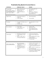
Troubleshooting Spectra Connect Alarms 

SYMPTOMS 

PROBABLE CAUSE 

REMEDY 

Summary of Contents for LB-20000

Page 1: ...220 S McDowell Blvd Petaluma CA 94954 Phone 415 526 2780 Fax 415 526 2787 techsupport spectrawatermakers com www spectrawatermakers com Updated March 7 2018 LB 20 000 Containerized Watermakers with Sp...

Page 2: ...2 Page Intentionally blank...

Page 3: ...ation 30 Manual operation 33 Other Operating Modes 37 Auto Store 38 Spectra Connect Settings 54 Long Term Storage Procedures 39 Maintenance 41 Membrane Cleaning Procedures 46 Oil Changes 47 Tube fitti...

Page 4: ...4 Page Intentionally blank...

Page 5: ...Spectra Connect Quick Start Guide Run Mode Select your desired Run Mode to start mak ing water and filling your tanks See details on Run Mode options on p 37 Spectra Connect Modes and Definitions Aut...

Page 6: ...the carrier within 24 hours of re ceiving goods LB 20k system shipping list This system is two independent LB 10000 units built into a custom fiberglass stand and installed into a 20ft ISO Shipping C...

Page 7: ...for more detailed instructions The main valve panel for each LB 10 000 watermaker is identical and all the valves and gauges are clearly labeled The system contains both pressure transducers for the S...

Page 8: ...elief Valve Membrane pressure Gauge Electric Fresh water flush valve Manual fresh water flush valve The Valve and Gauge panel Both of the watermakers are identical and are capable of fully automatic o...

Page 9: ...hlorine when the unit is mak ing product water the injection pump is powered when the diversion valve is open The manufac turers operation manual is in the binder Media filters Each system has two med...

Page 10: ...uality Note that measuring the chlorine concentration should be measured from the product tank as the chlorine injec tion point is too close to the sampling valve for ade quate mixing The black ABS Dr...

Page 11: ...left and pressurized chlorinated water back from the storage tank The top connection is the drain that is connected to the brine discharge from both wa termakers and the back flush drain from all four...

Page 12: ...ed Water Flow Gauge Cartridge Filter Array Flush Valve SP 20 Energy Recovery Pump Pressurized Fresh water from tank Fresh water Storage tank by others Product water Charcoal filter Fresh Wa ter Pump b...

Page 13: ...and will self prime up to 10ft 3m The pipe runs for each of the two systems should be at least 1 1 2 up to 50 ft 15m and be increased to 2 or more f it needs to be longer Please consult our applicati...

Page 14: ...filters so that water will drain out under the input output manifold plate built into the left side of the container Allow for drainage at the door and under the input output manifold with a gravel ca...

Page 15: ...s frame and if you need the unit to pump water over 10 ft install a transfer tank and a delivery pump It is not recommended to use the desalinator as a prod uct water delivery pump If the product wate...

Page 16: ...ntrol box The control system is designed to shut down when the tank switches close When tank is full both switches must be closed Note If tank switches are not used you must disable the tank switches...

Page 17: ...as necessary If you must extend the wires beyond 50 contact the factory to en sure proper operation Connect the Tank Level Sensor cables to the appropriate terminals in the control board inside the ma...

Page 18: ...ack on 4 Follow the screen prompts below 5 Note the Device IP address shown in and record the 10 digit numerical address on the front of this manual for future reference Note Your Spectra Connect is o...

Page 19: ...you press on your web browser will be controlling your watermaker Caution If operating your watermaker from a computer phone or tablet you must keep the tab open while the system is in operation and t...

Page 20: ...ing chemi cals Warning Damage will occur if the system is not purged of the storage chemicals before pressurizing the system Maintenance note Get into the habit of recording the pressures and flow rat...

Page 21: ...media filters Turn Boost pump switch to manual Push the switch on the right up to manual start and the pump will start adjust pressure with the dial to 25psi at the media filter gauges Follow the ins...

Page 22: ...ngers 6 Turn on the power to the system and the Spectra Connect screen will display Has the system been stored with chemicals Press Yes to start the Purge sequence The system will purge the storage ch...

Page 23: ...ase the Boost Pressure rotate the dial on the Boost Pump Speed Control 9 Using the buttons on top of the filter housings bleed out the air in the filter housings until water is coming out 10 Check the...

Page 24: ...case there is any residual chemicals in the membrane Carefully inspect for leaks over the entire system Shut down the sys tem and repair any leaks you find 13 After the Product Purge cycle completes t...

Page 25: ...sed add 565grams of 65 hypochlorite then top off the tank with fresh water Make adjustments to the Stroke Rate strokes per mi nute and Stroke Length amount per stroke while the unit is running Start w...

Page 26: ...ew filters are in place before proceeding 2 Follow the steps in Figures 1 4 below to initiate the Calibration Sequence Sensor Calibration Many of the settings on your system have been pre calibrated d...

Page 27: ...Follow the steps below to enter the calibration se quence for the optional Tank Level Sensor s The tank needs to be full to proceed with the calibration process and you need to measure the approximate...

Page 28: ...uring testing and is not normally required during commissioning If the product quality is not reading accurately follow calibration steps A handheld salinity meter or other reliable device is required...

Page 29: ...ouch the Gal Liter field to enter the volume of the container used 6 Touch the Minutes field to enter the minutes it took to fill the container Only enter the minutes ex 3 min 15 sec should be entered...

Page 30: ...he pump plungers 3 Press the Start button then select the desired operating mode 4 Runs your watermaker until the Tank Full switch closes fresh water flushes the system then goes into Auto Store mode...

Page 31: ...the Di version Valve opens allowing water to enter the tanks and the screen image changes Verify that the system is operating according to the factory specifications detailed on p 36 See the Troubles...

Page 32: ...s tem will enter standby mode waiting for the next run cycle Installation note If the feed tank water level is above the drain then it may be necessary to close the feed valve when the fresh water flu...

Page 33: ...mps feed pump Pearson pump and chlorine injection pump 1 Confirm the inlet valve and the brine discharge valves are in the RUN position The Brine Discharge valve handle should point up The Feed water...

Page 34: ...e middle of the lid to push it down while tightening the lid Note if the pump bowls do not fill per the above remove the lid and fill the bowl com pletely with water This should allow the pump s to pr...

Page 35: ...wise to open the valve so product water will flow to the storage tank 11 Flip the switch on the control box for the Chlorine Injection so it will run manually Chlorine is not injecting if the light is...

Page 36: ...lip the toggle switch to SERVICE 11 Allow the system to flush until the brine discharge is 1000ppm salinity about 5 minutes You can check this by holding a container under the brine discharge service...

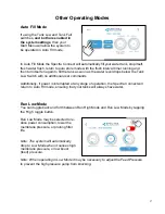
Page 37: ...tional user commands Additionally if power is interrupted at any stage of operation the Spectra Connect will return to Auto Fill mode ensuring that your tanks will always have water Run Low Mode You c...

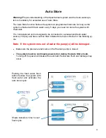
Page 38: ...pressurized fresh water source 50 psi and has a carbon filter included to remove chlorine for the flushing cy cle Note If the system runs out of water the pump s will be damaged Make sure the pressur...

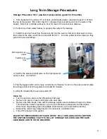
Page 39: ...tions System Storage for up to 6 months Pickling If the system is to be left unused for more than 2 weeks perform the following storage procedure The procedure introduces a chemical compound SC 1 into...

Page 40: ...toggle switch on the main control box to Service to turn on the pump and circulate the storage chemical in the system for at least 20 minutes 6 After 20 minutes flip the service switch off Clean Up T...

Page 41: ...f the system including the feed water supply pump Open the housings and discard old filters Clean out the housing bowls check and lubricate the o rings with silicone grease and reassemble the housings...

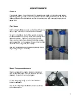
Page 42: ...to each use or when the pressure drop across them increases by 5 10psi See media filter manual for detailed instructions Replace the media every 10 years or when the media filters lose effectiveness F...

Page 43: ...ble Each time you start the watermaker open the oiler lever pointing up and allow 4 5 drips to fall Unscrew the top of the oiler to increase the drip rate Be sure to close the valve to limit the amoun...

Page 44: ...will need to be replaced every 6 12 months based on usage and duty cycle There are test strips that should be used on a regular basis daily while learning how the system responds to local conditions t...

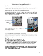
Page 45: ...espond to both cleanings this is an indication of another problem with the system or that it is time to replace the membranes Contact Spectra Watermakers before removing a membrane If known bio foulin...

Page 46: ...system for at least 20 minutes 6 After 1 hour turn the service switch off If the cleaning solution cannot be heated to 120 F 45 C then allowing the solution to soak for several hours will increase ef...

Page 47: ...appears milky Note that if the oil appears milky it is time to change the seals as water is get ting into the crankcase from the pump head There is a dip stick at the back of the crankcase to check th...

Page 48: ...48 Black Parker tube fittings...

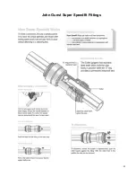
Page 49: ...49 John Guest Super Speedfit Fittings...

Page 50: ...ate permeate flow meter Replace seals Replace Damper Piston and Seal Replace Pistons and Seals Check membrane pressure against nominal system parameters Recovery Ratio Increasing Worn Pistons Permeate...

Page 51: ...or display system does not operate Display has gone to sleep Remote display not con nected No power to control box Touch the screen to wake it up Check display cable connections at back of display and...

Page 52: ...e Clean membrane High Pressure Blocked brine discharge or product line Fouled membrane Re starting No signal from Rotoflow meter at startup System airlocked See remedy above for system stalled Service...

Page 53: ...iving IP address from router or switch Connect the control board to a router or switch according to the Networking instructions Cycle power on the water maker with the network cable connected Power su...

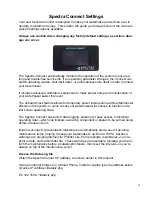
Page 54: ...effects on the system In some cases your watermaker will continue to function in its last known operating state The Spectra Connect has built in data logging allowing for easy access to historical op...

Page 55: ...n sor System stalled alarms occur when the control board does not sense any product water being pro duced and shuts down to protect the pump from running dry Poor Quality Fault Disables the High Salin...

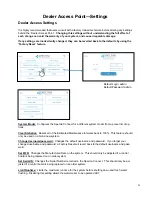
Page 56: ...op tions Clear Statistics Resets all of the Estimated Maintenance Intervals back to 100 This feature should only be used on a brand new system Change Username password Changes the default username and...

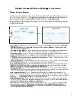
Page 57: ...ining in the tank and the tank switches which allow the system to turn on off automatically Boost Pressure Setup Enable alternate Boost Pressure sensors change the Low Vacuum Limit or Boost Pressure S...

Page 58: ...ables an optional power sensor after it is installed PH ORP Enables an optional pH or ORP meter after it is installed Z Ion Enables or Disables the optional Z Ion system after it is installed If the Z...

Page 59: ...rane endcap Check intake line for restrictions blockages or air leaks Close Pressure Relief Valve on Pump Confirm controller settings correct SERVICE PREFILTER FAULT The Service Prefilter fault is tri...

Page 60: ...esent in flush water They must be of proper specification to be suitable There is no test for chlorine dam age except the process of elimination of other causes DIRTY OR SCALED membranes A dirty forei...

Page 61: ...or by Pickling your membrane Keeping the prefilters clean is also im portant in preventing bio fouling If your prefilters are allowed to become a breeding ground for bacteria get smelly the contaminat...

Page 62: ...of the detergent Run the sys tem unpressurized with pressure relief valve open with the watermaker drawing water from the bucket and discharging overboard When about half the water is gone from the bu...

Page 63: ...n overnight These bacteria can spread throughout the watermaker and begin to grow on the membrane causing poor water quality and high feed pressures Flushing the system with fresh water after every us...

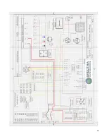
Page 64: ...64...

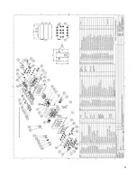
Page 65: ...65...

Reviews: