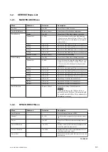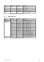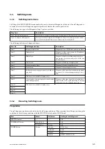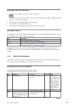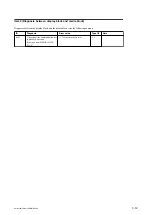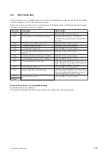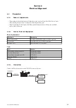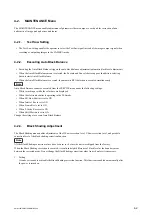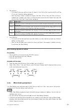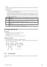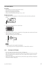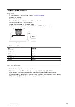
Error value
Diagnosis
10
Path: Pin L1 → pin P7
Data: sine wave (1 kHz)
Starting serial input channel: Channel 1
Starting serial output channel: Channel 1
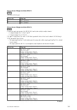
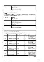
Error values of diagnosis items ID 0x15
Note
The signal is input to IC501 (pin M14) on the AU-342 board and is output from IC501 (pin number: shown below) to
IC1700 on the DCP-61 board (pin number: shown below).
Error value
Diagnosis
1
Path: Pin A2 → pin G22
Data: 0x55550000
Starting serial output channel: Channel 4
2
Path: Pin A2 → pin G22
Data: 0xaaaa0000
Starting serial output channel: Channel 4
3
Path: Pin A3 → pin H22
Data: 0x55550000
Starting serial output channel: Channel 6
4
Path: Pin A3 → pin H22
Data: 0xaaaa0000
Starting serial output channel: Channel 6
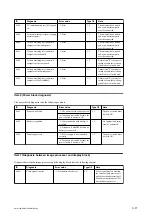
Item5 (System controller block diagnosis)
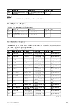
The system controller block diagnosis tests the following contents.
ID
Diagnosis
Error value
Type1/2
Note
0x01
I
2
C communication test (RTC)
-1: Error
1, 2
The unit must have started
and a sub-microcomputer
must be connected.
0x02
I
2
C communication test (EEPROM)
-1: Error
1, 2
The unit must have started
and a sub-microcomputer
must be connected.
0x03
I
2
C communication test (power sup-
ply microcomputer)
-1: Error
1, 2
The unit must have started
and a sub-microcomputer
must be connected.
0x04
I
2
C communication test (sub-micro-
computer of the inside panel)
-1: Error
1, 2
The unit must have started
and a sub-microcomputer
must be connected.
0x05
I
2
C communication test (sub-micro-
computer of the handle)
-1: Error
1, 2
The unit must have started
and a sub-microcomputer
must be connected.
0x06
I
2
C communication test (sub-micro-
computer of the rear panel)
-1: Error
1, 2
Normal end "0" is always re-
turned because there is no ap-
plicable device in this unit.
0x07
I
2
C communication test (sub-micro-
computer of the outside panel)
-1: Error
1, 2
Normal end "0" is always re-
turned because there is no ap-
plicable device in this unit.
0x08
I
2
C communication test (sub-micro-
computer of the viewfinder)
-1: Error
1, 2
Normal end "0" is always re-
turned because there is no ap-
plicable device in this unit.
Continued
PMW-160/PMW-150/PMW-EX260
3-10
Summary of Contents for XDCAM PMW-160
Page 1: ...SOLID STATE MEMORY CAMCORDER PMW 160 PMW 150 PMW EX260 SERVICE MANUAL 1st Edition ...
Page 4: ......
Page 8: ......
Page 10: ......
Page 30: ......
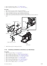
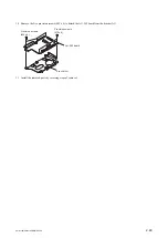
Page 38: ...3 Install the removed parts by reversing steps of removal PMW 160 PMW 150 PMW EX260 2 8 ...
Page 92: ......
Page 128: ......
Page 130: ......
Page 131: ......


