3.
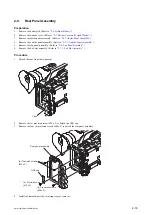
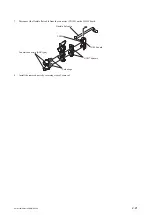
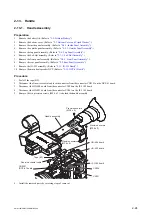
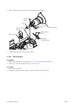
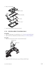
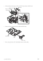
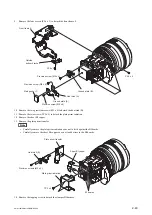
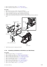
Remove the two claws to detach the DET-55 board.
Claws
Claws
DET-55 board
CN100
Harness
Panel hinge cabinet B
Panel hinge cabinet T
Precision screws (M2 x 5)
4.
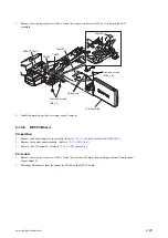
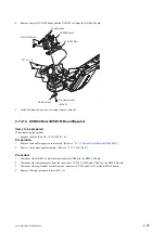
Install the removed parts by reversing steps of removal.
2-13-7. LCD Panel
Preparation
1.
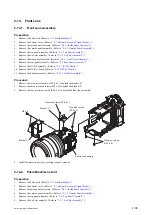
Remove the handle (upper) case assembly. (Refer to
“2-13-2. Control Switch Block (GZ92000)”
.)
2.
Remove the control panel assembly. (Refer to
.)
3.
Remove the LCD assembly. (Refer to
Procedure
1.
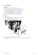
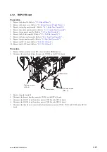
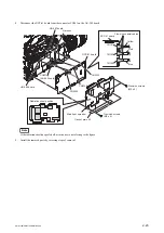
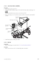
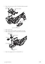
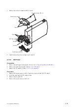
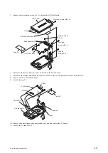
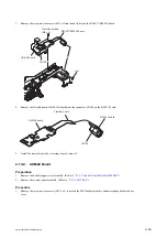
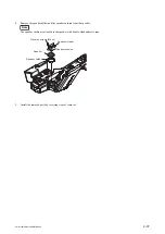
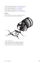
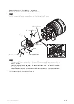
Remove the two precision screws (M2 x 5) and the two claws to detach the LCD cabinet.
2.
Peel off the tape 50 and the LCD conductive tape.
3.
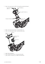
Remove the main gasket (H).
4.
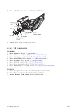
Remove the two precision screws (M2 x 4).
PMW-160/PMW-150/PMW-EX260
2-30
Summary of Contents for XDCAM PMW-160
Page 1: ...SOLID STATE MEMORY CAMCORDER PMW 160 PMW 150 PMW EX260 SERVICE MANUAL 1st Edition ...
Page 4: ......
Page 8: ......
Page 10: ......
Page 30: ......
Page 38: ...3 Install the removed parts by reversing steps of removal PMW 160 PMW 150 PMW EX260 2 8 ...
Page 92: ......
Page 128: ......
Page 130: ......
Page 131: ......

