2-10. IFC-13 Board
Preparation
1.
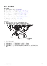
Remove the battery lid. (Refer to
2.
Remove the bottom cover. (Refer to
“2-3. Bottom Cover and Tripod Washer”
.)
3.
Remove the outside panel assembly. (Refer to
“2-5-1. Outside Panel Assembly”
.)
Procedure
1.
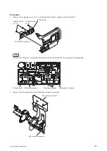
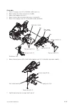
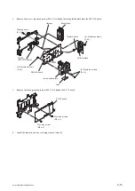
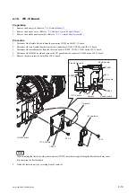
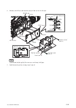
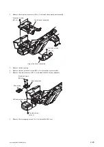
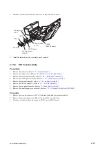
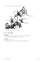
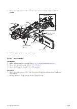
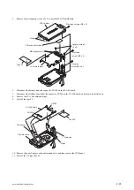
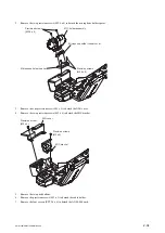
Disconnect the flexible flat cable from the connector CN502 on the IFC-13 board.
2.
Disconnect the two flexible boards from the two connectors CN201, CN202 on the IFC-13 board.
3.
Disconnect the three harnesses from the three connectors CN204, CN303, CN401 on the IFC-13 board.
4.
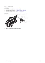
Disconnect the HN-402 board and remove the CN guard from the connector CN400 on the IFC-13 board.
5.
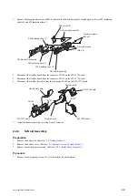
Remove the three screws to detach the IFC-13 board.
IFC-13 board
Flexible flat cable
Flexible board
Flexible board
Flexible board
CN401
CN502
CN201
CN202
CN203
Harness
CN400
P2 x 4
P2 x 4
IFC-13 board
IFC protector
HN-402 board
CN guard
Note
When installing the flexible board to the connector (CN202), note that strongly folding the flexible board may cause
disconnection the flexible board.
6.
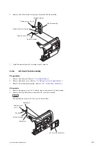
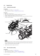
Install the removed parts by reversing steps of removal.
PMW-160/PMW-150/PMW-EX260
2-19
Summary of Contents for XDCAM PMW-160
Page 1: ...SOLID STATE MEMORY CAMCORDER PMW 160 PMW 150 PMW EX260 SERVICE MANUAL 1st Edition ...
Page 4: ......
Page 8: ......
Page 10: ......
Page 30: ......
Page 38: ...3 Install the removed parts by reversing steps of removal PMW 160 PMW 150 PMW EX260 2 8 ...
Page 92: ......
Page 128: ......
Page 130: ......
Page 131: ......

