


3-15
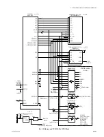
PCS-1500/1500P
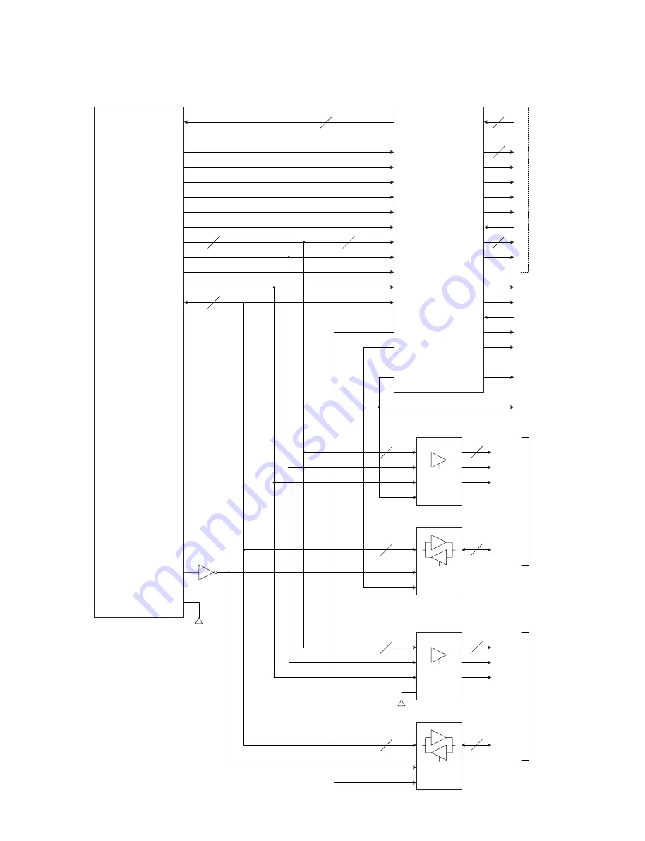
Fig. 3-7 System Bus I/F of CPU Block
BUS Controller PLD(IC110)
M4LV128/64-12VC
CKIO
CLK
\CS4
\WE0
A
1
-A
3
,A
20
-A
24
\CS4
RD/WR
A
0
-A
25
D
0
-D
15
\WE0
\RD
30MHz
\IOCS16
LVHD
0-15
LVHA
1-7
\LVWR_P
\LVHRD
Buffer(IC106,107)
LVC244 or LCX244,WH125
\G
D
0
-D
15
\G
DIR
\CS1
\CS1
\CS5
\CS5
\RD
\IRL0-3
\IRL0-3
\CS6
\CS6
4
9
10
D
0
-D
7
\WE1
\WE1
HD
0-15
HA
1-5
\HWR
\HRD
Buffer(IC109)
LVC244 or LCX244
\G
D
0
-D
15
\G
DIR
\DEN5
\DEN3
STANDBY
\HCS_x
\HRD_VCP
\HWR_VCP
IRQ_x
\RES_x
\WAIT_PCM
RES_PCM
\DEN_PCM
5V-
Bus
3.3V-
Bus
\DEN_OP
CPU(IC100)
HD6417708S
Transceiver(IC105)
LVC245 or LCX245
Transceiver(IC108)
LVC245 or LCX245
Vcc=3.3V-2
Vcc=3.3V-2
Vcc=3.3V
Vcc=3.3V
\BS
\BS
\HWR_GOA
7
SLEEP
\PWD_AK
\WAIT_OP
PWR_PCM
\RD_PCM
Vcc=3.3V
Vcc=3.3V
Some of these
are connected
to BusSwitch
(IC111,112)
26
8
7
5
5
7
32
16
16
16
16
3-2. Circuit Description of the Respective Boards
Summary of Contents for PCS-1500
Page 8: ......
Page 75: ...1 67 PCS 1500 1500P Sony Corporation Printed in Japan ...
Page 76: ......
Page 130: ......
Page 198: ......