73
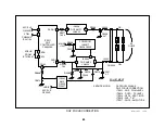
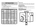
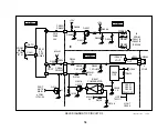
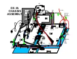
Front of TV
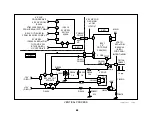
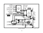
D Board
FBT
CN6506
8
10
Q8009
D6017
IC6007
CN5505
A Board
IC6007
I
O
G
n/c
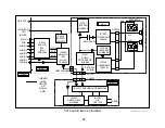
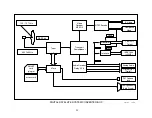
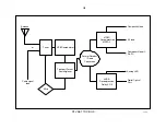
Self Diagnostic Block
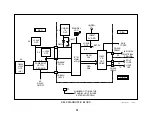
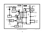
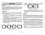
The Self-Diagnostic circuit is a program of the Main uCom IC on the A
board. This program monitors seven general faults that result in one or
more of the following:
♦
TV shutdown (AC relay is turned off);
♦
TV Latched OFF** (AC relay is held off); or
♦
A dark picture (no RGB signal).
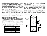
As an indication of failure, the Main uCom blinks the Standby LED a num-
ber of times, pauses, then repeats.
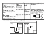
Faults Monitored by Main uCom IC
Stby
LED
Blinks
Symptom
Bd
Monitored
Circuit
Test point
(verification)
Normal
Voltage
0 X
Shutdown
D
+200V
OCP (HV)
Q8009/C
0.1Vdc
2 X
Shutdown
D
+135V
OCP
CN6506/pin
8
0V
3 X
Shutdown
A
Unreg 7V
OVP
D6017/C
0V
3 X
Shutdown
D
+135V
OVP
CN6506/pin
7
0.1V
4 X
Shutdown
D
V Out
Loss
CN5505/pin
7
0.78V
5 X
Blanking
C/A
/G2
adj
IK balance
CN202/pin 8
3 pulses
in vertical
interval.
6X
Shutdown
A
Set 5V
OCP
IC6007/
Output
5.0Vdc
7X
Shutdown
D
H Out
OCP
CN5505/pin
8
0V
** TV latched OFF. Press power button twice to turn TV back on
OSD Diagnostics
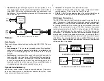
In addition to the blinking Stby LED, the Main uCom records the number
of times the failure occurred. This is useful when the user complains of
an intermittent shutdown.
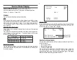
Access the Diagnostic Mode
To enter the test screen, first press these remote control buttons one at a
time:
Display
,
5
, Vol
—
, Power
On
.
The screen will list the circuit monitored and the number of times the
failure has occurred.
Clear the OSD Diagnostic numbers
To clear the number of failures from the test screen press:
Press
8, Enter
.
Summary of Contents for KV-32XBR400
Page 1: ......
Page 5: ...1 NOTES ...
Page 12: ...8 NOTES ...
Page 14: ...10 NOTES ...
Page 83: ...APPENDIX ...


