33
ch2
ch1
ch1: pkpk= 325 V
ch1: freq= 84.8kHz
CH1! 100 V=
CH2!5.00 V= MTB2.00us- 1.18dv ch1-
1
2
T
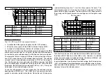
In the following scope shot both drive outputs from IC6001/pins 12 and 16
are shown. The outputs are complementary, the duty cycle is 50% and
the frequency has dropped down from 200kHz to about 85kHz.
Primary PS Oscillator - Normal operation - 85kHz
Channel
Name
Location
Voltage
1
Top Driver Output
Q6008/gate
340Vp-p
2
Bottom Driver Out
Q6007/gate
12Vp-p (4.6Vdc)
Time base = 2usec/div.
Testing
Checks for Primary power supply operation
Check Point
Normal
1. R6006
340Vdc
P.S. Input voltage
2. CN6005/ pin 5
>+15.6Vdc
Pri-Pre 15V. Checks P.S. Output
3. IC6001/ pin 2
(Feedback
voltage)
1.9Vdc
If step 2 voltage is low, measure
IC6001/pin 2. If pin 2 is High (4V) -
problem is around IC6001. If pin 2
is Low (0-1V), problem is the
feedback path IC6002, PH6001.
4. IC6001 voltages. See the next chart.
IC6001 Voltages (Power ON, Video 1 input, Dark screen)
1. 2. 3. 4. 5. 6. 7. 8. 9.
3.0V
1.8V
2.2V
2.5V
0V
0V
4.5V
18.4V
0V
10. 11. 12. 13. 14. 15. 16. 17. 18.
10V
0V
4.5V
-0.2V
-28V
-32V
-32V
-0.3V
313V
PM3394, FLUKE & PHILIPS
ch2
ch1
ch1: pkpk= 349 V
ch1: freq= 209kHz
CH1!79.9 V=
CH2!10.0 V= MTB1.00us- 1.28dv ch1+
1
2
T
Hot ground is at CN6501/pin 6 (black wire).
Oscillator Output Operation
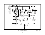
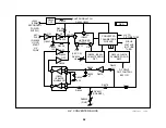
The details of how the oscillator develops output voltage in T6003 are
explained here. When the oscillator in IC6001 starts up (V Sense = 3V,
no feedback VC1 voltage yet), the signal is amplified using unregulated
voltage input pin 18 and a 200kHz signal is output IC6001/pins 12 and 16.
This is shown in the following waveform:
Primary PS Oscillator - Start Up = 209kHz
Channel
Name
Location
Voltage
1
Top Driver Output
IC6001/pin 16
340Vp-p
2
Bottom Driver Out
IC6001/pin 12
12Vp-p (4.6Vdc)
Time base = 1usec/div.
The two signals applied to the Q6008 and Q6007 drivers are complemen-
tary. This means only one MOSFET is conducting at a time. A positive
voltage applied to top MOSFET Q6008’s gate turns it ON so its Drain to
Source resistance drops, increasing the voltage to T6003’s primary wind-
ing. This voltage passes through the primary winding of T6003 into C6014.
As the increasing voltage charges C6014, a magnetic field is built up in
the primary of T6003. This magnetic field induces voltage into the sec-
ondary windings that is rectified to supply low voltages to the TV set.
The cycle continues when Q6008 turns OFF and Q6007 turns ON. The
charged C6014 discharges through the primary of T6003 and Q6007 to
ground. The cycle then repeats.
Summary of Contents for KV-32XBR400
Page 1: ......
Page 5: ...1 NOTES ...
Page 12: ...8 NOTES ...
Page 14: ...10 NOTES ...
Page 83: ...APPENDIX ...

