viii
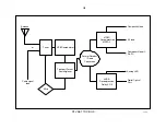
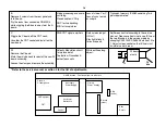
Board Replacement
Board Removal
Functions
Possible Failure
Symptoms
After board replacement
D
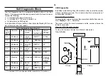
Slide chassis assembly back away from the
pix tube.
Remove 7 screws securing the board.
Slide the board toward the pix tube and tilt
up to access the flyback.
Unsolder the flyback.
Primary Power Supply
(+200V, +135V)
Protection latch circuit
HV Regulator circuit
Corner focus circuit
Top/bottom pincushion
circuit
H Output / V Output
Shutdown
Sides bowing in
♦
Transplant memory IC5501 containing
deflection parameters.
♦
Adj Focus (on FBT).
♦
Enter the service mode and perform touch
up geometry adjustments to D-
Conv/CXA8070 (group #6) and
CXA2026AS data (group #7)*.
♦
Adjust HV RV8002 for 31.5kV.
Adj HV shutdown RV8001 (coarse) and
RV8003 (fine) according to safety related
adj in the service manual.
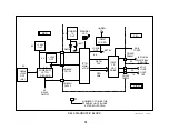
A
Remove 4 screws from the rear panel and
fold it down.
Pry the locks from connectors CN3202/3
while wiggling the B board away form the A
board.
Remove 6 screws securing the A board.
Lift the right side of the A board out.
Standby Power Supply
Degaussing circuit
Secondary Power Supply
(9V, 5V, 3.3V)
H & V Oscillators/Jungle
Both Tuners
Main uCom IC701
Audio processing
OSD (Menu)
Dead set (check
front panel master
switch).
♦
Transplant memory IC707 containing
system and user data.
♦
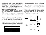
Enter the service mode and verify the TV
ID (group #19), then perform touch up
geometry adjustments to CXA2150D-1
data (group #4-1)*.
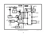
U
Remove 4 screws from the rear panel and
fold it down.
Pry the locks from its connector and wiggle it
Rear panel input connectors
Loss of video / audio
1-6 inputs. Tuner is
unaffected.
None
Summary of Contents for KV-32XBR400
Page 1: ......
Page 5: ...1 NOTES ...
Page 12: ...8 NOTES ...
Page 14: ...10 NOTES ...
Page 83: ...APPENDIX ...

