41
G2 Circuit
Operation
The G2 circuit controls the voltage to the screen grid of the CRT. The
higher the voltage the more electrons are accelerated in the gun struc-
ture, resulting in a brighter picture.
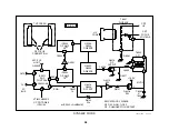
The source of the G2 voltage is approximately 1kV from the Horizontal
Output Transformer (T5001) secondary winding. The G2 control circuit
uses three transistors to shunt some of the G2 source voltage to ground.
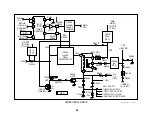
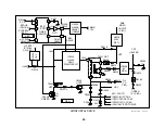
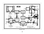
The remaining voltage is applied to the CRT’s G2 grid. A simplified dia-
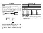
gram of this voltage divider is shown below:
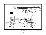
Within the shunt circuit are three transistors. Q9008 is used as a refer-
ence while Q9012 and Q9014 set the resistance to ground.
Rotating RV9002 varies the conduction of Q9012 and Q9014, and conse-
quently the shunt resistance. A lower shunt resistance produces a lower
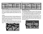
G2 voltage. The G2 voltage range of the screen control is listed in the
chart.
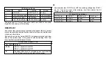
G2 (RV9002) Voltage Range
RV9002 Position
G2 Voltage
CCW
292.4Vdc
Normal
484Vdc
2/3 CW
590Vdc is maximum before shutdown
Operating Voltages
Normal Operating Voltages
Transistor
Collector
Base
Emitter
Q9002
10.9V
0V
0V
Q9008
12.0V
5.4V
4.8V
Q9012
10.4V
5.4V
4.8V
Q9014
438.5V
11.5V
10.9V
Automatic Video Mute
At power OFF, the Main uCom IC701 outputs a HIGH that turns on Mute
transistor Q9002. Q9002 lowers the G2 voltage, blanking the video when
the TV is shut off. The HIGH remains present as long as the TV is plugged
in (standby voltage is present).
CRT G2
voltage
Approx.
1kV from
the HOT
T5001/6
Resistor string
Shunt
Transistors
Q9014,
Q9012,
Q9008
G2 HV Adj
RV9002
Summary of Contents for KV-32XBR400
Page 1: ......
Page 5: ...1 NOTES ...
Page 12: ...8 NOTES ...
Page 14: ...10 NOTES ...
Page 83: ...APPENDIX ...


