v
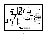
MODE
DATA
BUS
TRANSACTION
LAYER
LINK
LAYER
PHYSICAL
LAYER
VIDEO
AND
AUDIO
DATA
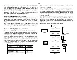
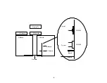
EXAMPLE: IEEE1394 INTERFACE IN CAMCORDER
CAMCORDER
100 Mb/s
PC
400 Mb/s
BANDWIDTH LIMITED BY SLOWER DEVICE
SCANNER
200 Mb/s
BANDWIDTH NOT LIMITED BY SLOWER DEVICE
SCANNER
200 Mb/s
CAMCORDER
100 Mb/s
PC
400 Mb/s
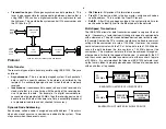
Transaction Layer –
Manages asynchronous data protocols. This
layer is also responsible for communicating between a device that is
using IEEE 1394, such as a digital camcorder or a capture card, and
the link layer. This would be the system control IC in a camcorder and
the PCI bus in a PC.
Protocol
Data Transfer
There are two types of data transfer possible using IEEE-1394. They are
as follows:
Asynchronous –
This is a memory mapped system. Each packet of
data is sent to a specific address to be stored and buffered by the
recipient. An acknowledge signal is sent when the data is properly
received.
Isochronous -
Isochronous data needs to be sent and received at a
steady rate that is in close timing with the ability of the receiving de-
vice to process the data. For example, if a digital camcorder pro-
cesses data at approximately 30 Mb/s, then the receiving device must
be able to use this data at the same rate. Data is essentially broadcast
at a predetermined rate and not checked for accuracy.
Dynamic Node Addressing
Each device, called a node, is assigned a specific address. This occurs
when a bus reset occurs or a new device is added to the system. Three
steps occur when these events occur:
IDs Cleared
- All previous ID information is erased.
Tree ID
- The device, which is the bus master, assigns each node a
specific address. This is called the Tree ID Process.
Self-ID
- After IDs have been assigned, the system allows time for
each device to identify itself to the other nodes in the network.
Multi-Speed Transactions
The IEEE-1394 allows for data transmission speed to vary over the net-
work. If necessary, a faster device will change its speed to communicate
with a slower one. The paths taken between devices also limit data rates.
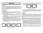
In Example A below, the PC or scanner would have no trouble communi-
cating with the camcorder at a rate of 100 Mb/s. However, the scanner
could not communicate with the PC at its top data rate of 200 Mb/s be-
cause the path between the two contains a 100 Mb/s device (the
camcorder). The maximum data rate that can be achieved through an-
other device is limited to the speed of that device. In example B, the PC
and the scanner would be able to communicate at the scanner’s top rate
of 200 Mb/s. It is very important that when an IEEE-1394 network is set
up that care is taken to properly place devices that need to communicate
with each other at top speeds.
Summary of Contents for KV-32XBR400
Page 1: ......
Page 5: ...1 NOTES ...
Page 12: ...8 NOTES ...
Page 14: ...10 NOTES ...
Page 83: ...APPENDIX ...

