21
c h3
c h2
c h1
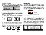
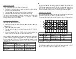
C H 1 !2 .00 V ~
C H 2 !2 .0 0 V = S T O P
C H 3 !2 .0 0 V = C H P M T B 2 0 .0 us line c h 1p
1
2
3
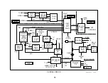
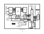
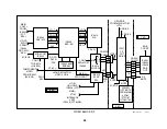
Video Block
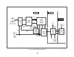
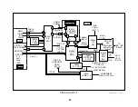
This Video Block Diagram will show the video signal processing as it
changes from an NTSC composite video signal to separate Y & C, com-
ponent Y, Pb, Pr and finally to RGB for the CRT cathodes.
Composite Signal Input (B Board)
The NTSC format video from one of the two tuners or video inputs 1-4 is
selected by composite video switch IC3201. The user makes the selec-
tion from the remote to the Main uCom IC701 through the I2C bus into
IC3201 (not shown).
There are three outputs from IC3201:
IC3201 Outputs
Name
Location
Output Type
Destination
Main
CN3201/pin 1
Composite or Y (if S
video input TV)
3D Comb filter
IC3501
Sub
IC3201/pin
56, 58
Separate Y / C
Y/C Sub
processor
Monitor
IC3201/pin
Composite
Rear panel output
Y & C Separation (B Board)
The main composite signal enters the BC board that plugs into the larger
B board. The 3D Comb filter separates the luminance from the chroma,
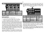
pixel by pixel to output Y and C signals. The input and outputs of the
Comb filter are accessible and shown as 2Vp-p signals with a DC compo-
nent in this scope shot:
3D Comb Filter - Color Bar input
Channel
Name
Location
Comments
1
Input
CN3201/pin 1
2Vp-p
2
Y Output
CN3201/pin 3
2Vp-p
3
C Output
CN3201/pin 5
1.7Vp-p
Time base = 20usec/div
Component Video Conversion (B Board)
The separate Y & C main signal is matrixed into component Y, Pb, and Pr
signals inside IC3048. This IC3048 can therefore act as a switch to choose
between the component video input from Video 5, Video 6 or the main
signal from the 3D Comb filter.
An additional RGB signal from the closed caption / V Chip IC3602 can be
matrixed into the signal path by IC3048 if these features are selected by
the user.
There are three outputs from IC3048:
IC3048 Outputs
Name
Output Type
Destination
Main Signal
Component
Main/Sub selector
H & V Sync
1Vp-p
Sync selector IC3004
Comp Video
1Vp-p
CCD/V Chip IC3602,
ID-1 IC3603
Comp Video / ID-1 Concept
ID-1 Concept
ID-1 is a relatively new concept. The ID-1 signal is hidden in the vertical
blanking area of the picture. This ID-1 signal identifies the aspect ratio of
the picture. IC3603 finds the signal and outputs data to the microproces-
sor. The micro can change the vertical or horizontal size to present the
picture properly. Recently, an ID-2 signal containing the aspect ratio and
copy guard information has been proposed.
Main Signal Path
The main component video and sync signals are sent to switches IC3002
(video) and IC3004 (sync). They switch between the main and sub pic-
tures. The outputs go to the Digital Reality Creation IC3303.
Summary of Contents for KV-32XBR400
Page 1: ......
Page 5: ...1 NOTES ...
Page 12: ...8 NOTES ...
Page 14: ...10 NOTES ...
Page 83: ...APPENDIX ...

