61
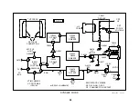
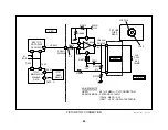
Convergence correction areas
TV screen
Correction
areas
Correction
areas
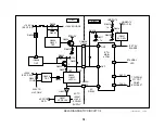
Convergence Circuit
Concept
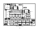
The purpose of the convergence circuit is to create a dynamic signal that
is applied to the convergence (CY) winding within the main yoke. The
convergence winding is positioned so the dynamic signal will move one or
two electron beams more than the third. This is how an electronic signal
can unite all three beams together on the screen. The convergence cir-
cuitry corrects at the four sides and right corners of the TV screen in this
TV.
Circuitry
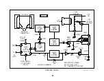
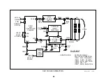
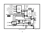
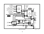
At power ON, convergence data stored in the Non-Volatile Memory IC707
is retrieved by Main uCom IC701 (not shown) and sent to IC5513 via the
I2C bus. Within ICI5513, this data shapes the vertical and horizontal
signal input to pins 3 and 14 and produces two outputs.
The H Stat output at IC5513/pin 8 corrects for left and right mis-conver-
gence. The V Stat output at IC5513/pin 9 corrects for top and bottom mis-
convergence. The two signals are combined externally and amplified by
IC5515 into a 10Vp-p waveform at the convergence yoke CN5510/pin 3.
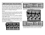
IC5513’s input and output signals are listed in the chart:
IC5513 s Input / Output Signals
Name
IC5513/pin
Voltage
Purpose
VTIM
3
1.8Vp-p, 4.8Vdc
Input Vert sawtooth
ramp
AFC-PLS
14
10Vp-p, 0.74Vdc
Input horiz pulse
Ref
5
5Vdc
reference for IC5515
H Stat
8
100 mV p-p
left/right conv. signal
V Stat
9
200 mV p-p
top/bottom conv. signal
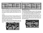
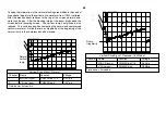
Convergence Output
Channel
Name
Location
Voltage
1.
VTIM (Vertical timing) input
IC5513/pin 3
1.8Vp-p
2.
Convergence Output
CN5510/pin 3
10Vp-p
Time Base = 5msec/div
CH1!1.00 V~ STOP ENV
CH2!5.00 V~ MTB5.00ms ch1+
1
2
T
Adjustment
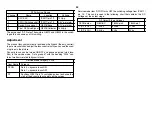
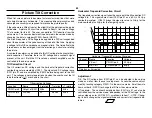
The convergence yoke signal is adjusted in the service mode. Data group
#6 with the heading “D-Conv” has nine adjustment parameters that cor-
rect for mis-convergence, mostly at the right side of the TV screen.
Summary of Contents for KV-32XBR400
Page 1: ......
Page 5: ...1 NOTES ...
Page 12: ...8 NOTES ...
Page 14: ...10 NOTES ...
Page 83: ...APPENDIX ...


