1-11
HSR-1/1P
HSR-2/2P
Chapter 2
Basic Operations
2-2
Chapter 2
Basic Operations
To prevent unintentional erasure
Set the REC/SAVE switch to the SAVE position.
To rerecord on a cassette
Return the REC/SAVE switch to the REC position. No recording will be
made on a cassette with the switch set to SAVE.
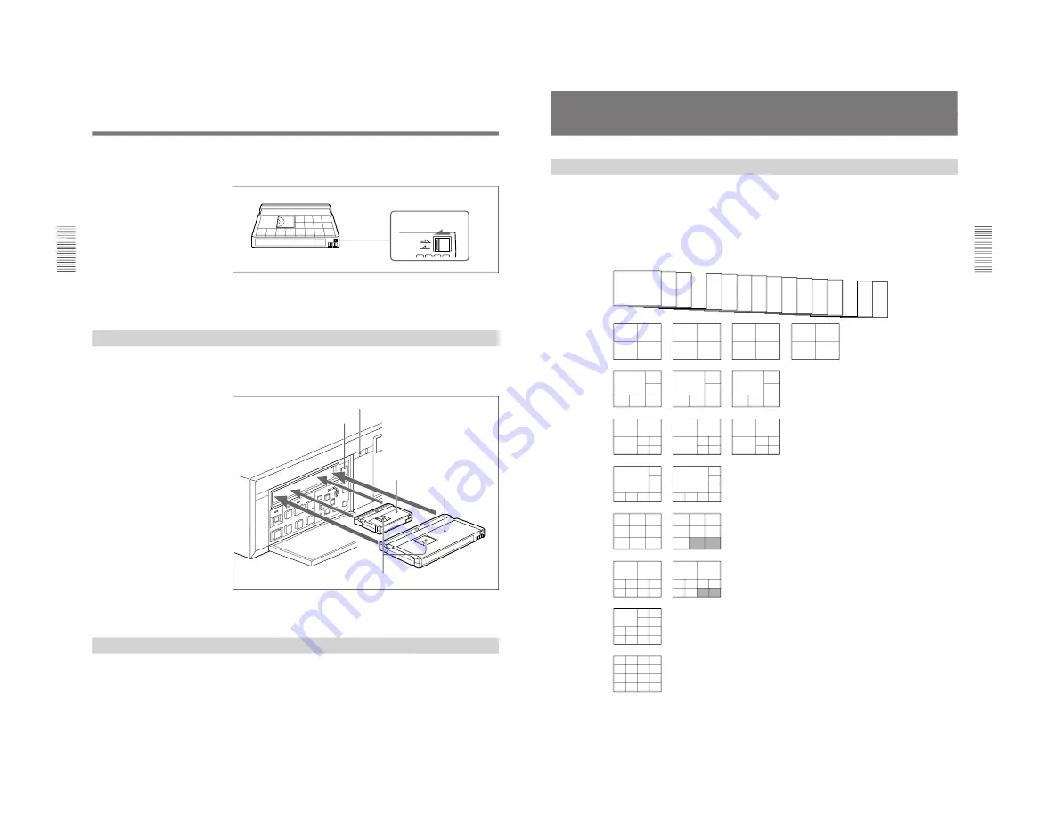
Inserting a Cassette
Insert/eject a cassette with the power on.
Open the front panel cover and insert the cassette through the opening as
shown below.
The cassette is automatically pulled into the operating position and the
cassette indicator lights up.
Ejecting a Cassette
Press the EJECT button.
The cassette indicator flashes while the cassette is being ejected.
Handling Cassettes
REC
SAVE
REC/SAVE switch
Set to SAVE.
EJECT button
Cassette indicator
Mini-sized cassette (Align it with
the concave portion at the center
of the opening.)
Standard-sized cassette
With the tape window facing upward
S
REC
EJECT
‚
§
·
º
¶
π
®
æ
†
Chapter 2
Basic Operations
Chapter 2
Basic Operations
2-3
Monitoring Picture
Dividing the Screen
In addition to the capability to show the picture from a specified camera on
the full screen, this recorder has a multiplexer function to divide the screen
into multiple divisions and permit you to view the pictures from multiple
cameras at a glance.
In screen division modes, you can select the respective number of pages
(the same divisions with different camera configurations) for monitoring.
The following camera numbers have been assigned at the factory.
Full screen
(16 pages)
4 divisions
(4 pages)
6 divisions
(3 pages)
7 divisions
(3 pages)
8 divisions
(2 pages)
9 divisions
(2 pages)
10 divisions
(2 pages)
13 divisions
(1 page)
16 divisions
(1 page)
Camera assignments
You can assign the connected cameras to any division
by using Moni Display Structure of the Image Control
menu.
For the assigning method, see “Setting the Display
Structures” on page 5-9.
Border lines
You can select whether the lines are to be displayed,
and if so, in black or in white on the Indication Control
menu.
Superimposing
According to settings made on the Indication Control
menu, various information, such as the camera
number/name, date/time, etc. can be superimposed
onto the signal input from a camera.
The type of superimposed characters can also be set.
See Chapter 4 “Menu Operation” for the Indication Control
menu and “Setting Camera Names” on page 5-8 for camera
names.
1
2
3
4
5
6
7
8
9
10
11
12
13
14
15
16
1
2
3
4
5
6
7
8
9
10
11
12
13
14
15
16
1
3
2
4
5
6
7
1
3
2
8
9
10 11
1
3
2
12 13
14 15
2
1
3
4
5
6
7
8
9
1
10
11
12 13 14 15
1
2
3
4
5
6
7
8
9
10
1
2
11 12 13 14
15 16
1
2
3
4
5
6
7
8
9
1
2
3
4
5
6
1
7
8
9
10
11
1
12
13
14
15
16
10
11
12
13
14
15
16
1
2
3
4
5
6
7
8
9
10 11 12 13
1
2
3
4
5
6
7
8
9
10 11 12
13 14 15 16
Page 1
Page 2
Page 3
Page 4
Page 1
Page 2
Page 3
Page 1
Page 2
Page 3
Page 1
Page 2
Page 1
Page 2
Page 1
Page 2
Summary of Contents for HSR-1
Page 70: ......
Page 112: ......
Page 116: ...6 4 HSR 1 1P HSR 2 2P 6 1 3 Loading Unloading 6 1 4 Manual Up Down the FL Block ...
Page 118: ...6 6 HSR 1 1P HSR 2 2P Attach the jigs ...
Page 123: ...6 11 HSR 1 1P HSR 2 2P PHASE ADJUSTMENT K PHASE ADJUSTMENT L PHASE ADJUSTMENT M ...
Page 152: ...6 40 HSR 1 1P HSR 2 2P 6 4 33 Roller Shaft Assembly and Roller Belt Removing Attaching ...
Page 153: ...6 41 HSR 1 1P HSR 2 2P 6 4 34 LID Opener Removing Attaching ...
Page 156: ...6 44 HSR 1 1P HSR 2 2P 6 5 ADJUSTMENTS AND CHECKS 6 5 1 Adjustment Position ...
Page 157: ...6 45 HSR 1 1P HSR 2 2P 6 5 2 Adjustment Order ...
Page 161: ...6 49 HSR 1 1P HSR 2 2P 4 Adjustment order ...
Page 170: ...6 58 HSR 1 1P HSR 2 2P 6 6 SERVICE MODE 6 6 1 Data Processing ...
Page 171: ...6 59 HSR 1 1P HSR 2 2P 6 6 2 Service Mode ...
Page 172: ...6 60 HSR 1 1P HSR 2 2P 6 6 3 System Control Adjustment ...
Page 173: ...6 61 HSR 1 1P HSR 2 2P ...
Page 174: ...6 62 HSR 1 1P HSR 2 2P ...
Page 175: ...6 63 HSR 1 1P HSR 2 2P 6 6 4 Servo System Adjustments ...
Page 176: ...6 64 HSR 1 1P HSR 2 2P 6 6 5 Video System Adjustments 6 6 5 1 RP 228 Board Adjustments ...
Page 177: ...6 65 HSR 1 1P HSR 2 2P ...
Page 178: ...6 66 HSR 1 1P HSR 2 2P ...
Page 179: ...6 67 HSR 1 1P HSR 2 2P ...
Page 180: ...6 68 HSR 1 1P HSR 2 2P 6 6 6 Location Diagram of Adjustment Related Parts ...
Page 181: ...6 69 HSR 1 1P HSR 2 2P ...


