background image

19

G

e

tti

n

g

 st
ar

te

d

Setting the date and time

,

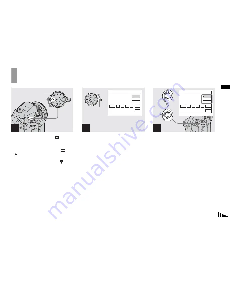
Set the mode dial to 

.

You can carry out this operation even when the 
mode dial is set to P

S

A

M

SCN

 or 

.

To set the time and the date again, set the mode 
dial to SET UP, select [Clock Set] in 

 (Setup 

2) (pages 48, 142), then proceed from Step 

3

.

,

Slide the POWER switch in the 
direction of the arrow to turn 
on the power.

The POWER lamp lights in green and the 
Clock Set screen appears on the screen.

,

Select the desired date format 
by moving the multi-selector to 

v

/

V

, then press the center.

You can select from [Y/M/D] (year/month/
day), [M/D/Y], and [D/M/Y].

If the rechargeable button battery, which 
provides the power for saving the time data, is 
ever fully discharged (page 144), the Clock Set 
screen will appear again. When this happens, 
reset the date and time by starting from Step 

3


above.

1

Mode dial

2

Clock  Set

2003

1

1

/

/

D/M/Y

M/D/Y

Y/M/D

00

AM

OK

Cancel

12 :

POWER 
switch

3

2003

1

1

/

/

00

AM

Clock  Set

D/M/Y

M/D/Y

Y/M/D

OK

Cancel

12 :

Summary of Contents for Cyber-shot DSC-F828

Page 1: ...Revision History Ver 1 0 2003 12 LEVEL 1 Link SELF DIAGNOSIS FUNCTION ORNAMENTAL PARTS SPECIFICATIONS SELF DIAGNOSIS FUNCTION ORNAMENTAL PARTS SPECIFICATIONS Link US Model Canadian Model AEP Model UK Model E Model Hong Kong Model Australian Model Korea Model Tourist Model Chinese Model Japanese Model DSC F828 ...

Page 2: ...der LCD panel used 1 1 cm 0 44 type TFT drive Total number of dots 235 200 980 240 dots Power general Used battery pack NP FM50 Power requirements 7 2 V Power consumption during shooting with LCD screen on 2 2 W Operating temperature range 0 to 40 C 32 to 104 F When using the Microdrive 5 to 40 C 41 to 104 F Storage temperature range 20 to 60 C 4 to 140 F Dimensions lens W end 134 4 91 1 157 2 mm ...

Page 3: ...or solder splashes and bridges 2 Check the interboard wiring to ensure that no wires are pinched or contact high wattage resistors 3 Look for unauthorized replacement parts particularly transistors that were installed during a previous repair Point them out to the customer and recommend their replacement 4 Look for parts which through functioning show obvious signs of deterioration Point them out ...

Page 4: ... Checking of lens drive circuit Cause Trouble with hardware The type of memory stick that cannot be used by this machine is inserted Data is damaged Unformatted memory stick is inserted Abnormality when flash is being charged When failed in the focus initialization Caution Display During Error SYSTEM ERROR MEDIA ERROR Flash LED Flash display Flashing at 3 2 Hz Self diagnosis display C ss ss The co...

Page 5: ...dom required for routine service Some delay should be anticipated when ordering these items The parts numbers of such as a cabinet are also appeared in this section Refer to the parts number mentioned below the name of parts to order 1 ORNAMENTAL PARTS LCD window adhesive sheet 3 087 155 01 Jack cover 3 087 153 01 LCD window 3 086 480 01 ...

Page 6: ...odel Note The components identified by mark 0 or dotted line with mark 0 are critical for safety Replace only with part number specified Note Les composants identifiés par une marque 0 sont critiques pour la sécurité Ne les remplacer que par une pièce portant le numéro spécifié Power cord Main lead 1 AEP E model 0 1 769 608 11 Power cord Main lead 1 AUS model 0 1 696 819 11 Power cord Main lead 1 ...

Page 7: ...DSC F828 8 Sony EMCS Co 2003L1600 1 2003 12 Published by DI CS Strategy Div 9 876 279 41 ...

Page 8: ...ony Corporation Getting started ________________________ Shooting still images __________________ Viewing still images ___________________ Deleting still images___________________ Before advanced operations _____________ Advanced still image shooting____________ Advanced still image viewing_____________ Still image editing ______________________ Still image printing______________________ PictBridg...

Page 9: ...eption which can be determined by turning the equipment off and on the user is encouraged to try to correct the interference by one or more of the following measures Reorient or relocate the receiving antenna Increase the separation between the equipment and receiver Connect the equipment into an outlet on a circuit different from that to which the receiver is connected Consult the dealer or an ex...

Page 10: ...used If the plug supplied with this equipment has a detachable fuse cover be sure to attach the fuse cover after you change the fuse Never use the plug without the fuse cover If you should lose the fuse cover please contact your nearest Sony service station This product has been tested and found compliant with the limits sets out in the EMC Directive for using connection cables shorter than 3 mete...

Page 11: ...e tiny black points and or bright points white red blue or green in color that constantly appear on the LCD screen and the LCD finder These points are normal in the manufacturing process and do not affect the recording in any way Be careful when placing the camera near a window or outdoors Exposing the LCD screen the finder or the lens to direct sunlight for long periods may cause malfunctions Do ...

Page 12: ...demark of SanDisk Corporation Microdrive is a registered trademark of Hitachi Global Storage Technologies in the United States and or other countries In addition system and product names used in this manual are in general trademarks or registered trademarks of their respective developers or manufacturers However the or marks are not used in all cases in this manual About the Carl Zeiss lens This c...

Page 13: ...ur camera 39 Viewing images on a TV screen 41 Deleting images 43 Formatting a recording medium 45 How to setup and operate your camera 47 Changing menu settings 47 Changing items in the SET UP screen 48 How to use the command dial 48 Deciding the still image quality 49 Creating or selecting a folder 50 Creating a new folder 50 Selecting the recording folder 51 Manual features to photo shooting sit...

Page 14: ...arging an image Playback zoom 84 Recording an enlarged image Trimming 85 Playing back successive images Slide show 85 Rotating still images Rotate 86 Playing back images shot in Multi Burst mode 87 Playing back continuously 87 Playing back frame by frame 87 Protecting images Protect 89 Changing image size Resize 90 Choosing images to print Print DPOF mark 91 Connecting to a PictBridge printer 93 P...

Page 15: ... to your computer For Macintosh users 117 Troubleshooting 119 Warnings and messages 130 Self diagnosis display If a code starting with an alphabet letter appears 133 The number of images that can be saved shooting time 134 Menu items 137 SET UP items 140 Precautions 143 The Memory Stick 144 The Microdrive 145 On InfoLITHIUM battery pack 146 Specifications 147 Display window 149 The LCD finder scre...

Page 16: ...ing 30 I Manual focus ring 67 1 2 3 4 5 6 7 8 9 q qa w ql qk qj qh qg qf qd qs J Flash emitter 34 K Infrared ray emitter 77 L Speaker M Advanced accessory shoe 71 N OPEN FLASH switch 69 O Metering mode button 58 P Flash button 68 Q BRK Burst Bracket button 63 75 76 R Macro button 33 S NIGHTSHOT NIGHTFRAMING button 77 T FOCUS AUTO MANUAL switch 67 Pressing the Display window backlight button turns ...

Page 17: ...in auto adjustment mode P To shoot still images in program auto mode S To shoot in shutter speed priority mode A To shoot in aperture priority mode M To shoot in manual exposure mode SCN To shoot in Scene Selection mode SET UP To set the SET UP items To shoot movies To view or edit images K AE LOCK Delete button 43 62 L Command dial 48 M OPEN CF lever 23 N CF card cover 23 O CF card eject lever 24...

Page 18: ... Finder adjustment lever 29 D FINDER LCD switch 29 E Screen status button 30 F Self timer Index button 34 40 G POWER lamp 18 H POWER switch 18 I Digital zoom Playback zoom button 30 84 J 7 Quick review button 29 1 2 3 4 5 6 7 8 9 q ...

Page 19: ... I Hook for shoulder strap Use the ACC accessory jack to connect an external flash or the remote control tripod Use a tripod with a screw length of less than 5 5 mm 7 32 inch You will be unable to firmly secure the camera to tripods having longer screws and may damage the camera 1 2 3 4 5 6 7 8 9 Attaching the lens cap and the shoulder strap Lens cap Shoulder strap ...

Page 20: ...od and the x mark on the lens and attach the hood to the lens 2 Turn the lens hood clockwise until it clicks Storing the lens hood The lens hood can be attached in the reverse direction to store it with the camera when it is not in use 1 Position the lens hood as shown below by aligning the mark on the lens hood and the x mark on the lens and attach the hood to the lens 2 Turn the lens hood clockw...

Page 21: ... firmly inserted all the way then close the cover The battery pack is easily inserted by pushing the battery eject lever at the front of the battery compartment to the front side Open the jack cover and connect the AC Adaptor supplied to the DC IN jack of your camera Open the cover in the arrow direction as illustrated above Connect the plug with the v mark facing up Do not short the DC plug of th...

Page 22: ...e battery eject lever in the direction of the arrow and remove the battery pack Be careful not to drop the battery pack when removing it Battery remaining indicators The battery remaining indicators on the screen or on the display window show the remaining shooting or viewing time The battery remaining time on the screen or on the display window may not be correct under certain circumstances or co...

Page 23: ... size The number of images and the battery life that can be recorded viewed are decreased under the following conditions The surrounding temperature is low The flash is used The camera has been turned on and off many times The zoom is used frequently The NightShot or NightFraming function is activated LCD Backlight or EVF Backlight is set to Bright in the SET UP settings The battery power is low T...

Page 24: ...d to a wall outlet wall socket When you have finished using the AC Adaptor disconnect it from the DC IN jack of the camera and the wall outlet wall socket The set is not disconnected from the AC power source mains as long as it is connected to the wall outlet wall socket even if the unit itself has been turned off 2 2 To a wall outlet wall socket Power cord mains lead 1 Using your camera abroad Po...

Page 25: ...e battery pack is being used to power the camera the Auto Power Off function will not work Movies are being played back A slide show is being shown A cable is connected to the USB jack or the A V OUT MONO jack How to use the multi selector To change the current settings of the camera bring up the menu or the SET UP screen pages 47 48 and use the multi selector to make the changes When setting up t...

Page 26: ... in green and the Clock Set screen appears on the screen Select the desired date format by moving the multi selector to v V then press the center You can select from Y M D year month day M D Y and D M Y If the rechargeable button battery which provides the power for saving the time data is ever fully discharged page 144 the Clock Set screen will appear again When this happens reset the date and ti...

Page 27: ... 5 until all of the items have been set If you select D M Y in Step 3 set the time on a 24 hour cycle 12 00 AM stands for midnight and 12 00 PM stands for noon Move the multi selector to B to select OK then press the center The date and time are set and the clock will start to keep time To cancel the setting process select Cancel then press the center 4 2003 1 1 00 AM Clock Set D M Y M D Y Y M D O...

Page 28: ... a recording medium You can use a Memory Stick Microdrive or CompactFlash card CF card as a recording medium Microdrive Hitachi Global Storage Technologies Inc DSCM 11000 1 GB We have checked the compatibility of CF cards compliant with CompactFlash Type I and Type II however we cannot guarantee proper operation of all CF cards Memory Stick Microdrive CompactFlash Switching the recording medium Se...

Page 29: ...it as far as it can go If you do not insert it correctly a proper recording or playback may not be carried out Close the battery Memory Stick cover To remove the Memory Stick Open the battery Memory Stick cover then push the Memory Stick to pop it out Whenever the access lamp is lit the camera is recording or reading out an image Never remove the Memory Stick or turn off the power at this time The...

Page 30: ...Microdrive CF card all the way in as shown in the illustration Whenever you insert a Microdrive CF card push it as far as it can go If you do not insert it correctly a proper recording or playback may not be carried out Close the CF card cover Close the CF card cover properly otherwise you cannot record or play back images using the Microdrive CF card 1 2 Front The v mark printed side 3 ...

Page 31: ...ccess lamp Setting the still image size Set the mode dial to and turn on the power then press MENU The menu appears You can carry out this operation even when the mode dial is set to P S A M SCN 1 8M 3 2 5M 3M 1M Image Size 8M Mode MENU Select Image Size by moving the multi selector to b B then select the desired image size by moving the multi selector to v V The image size is set After the settin...

Page 32: ... in Fine Standard 4 mode are shown below Units number of images 3 When Mode REC Mode is set to Normal For the number of images that can be saved in other modes see pages 134 135 4 For more information about the image quality compression ratio mode see page 49 Image size Examples 8M 1 3264 2448 For storing important images or printing A3 size or fine A4 size images 3 2 2 3264 2176 5M 2592 1944 For ...

Page 33: ...evices are played back the image size indication may be different from the actual image size When the images are viewed on the screen of the camera they all look the same size Number of shooting images can differ from these values according to shooting conditions When the remaining number of images recordable is more than 9999 9999 is indicated on the screen And when it is more than 999 999 is ind...

Page 34: ...s closer than this use the macro mode page 33 The frame indicated on the screen shows the focus adjustment range AF range finder see page 65 Press and hold the shutter button halfway down The camera beeps When the AE AF lock indicator stops flashing and remains on the camera is ready for shooting The screen may be frozen for a split second depending on the subject When the surroundings are dark th...

Page 35: ...mode However you can intentionally adjust the focus exposure etc In addition you can set the desired functions using the menu pages 47 and 137 S Shutter speed priority You can select the shutter speed page 55 In addition you can set the desired shooting functions using menus pages 47 and 137 A Aperture priority You can select the aperture value page 56 In addition you can set the desired shooting ...

Page 36: ...There are two Auto Focus functions AF range finder frame which sets the focus position according to the subject position and size and AF mode which sets when the camera starts and stops focusing on See page 65 for details Checking the last image shot Quick Review Press 7 quick review To return to shooting mode press the shutter button lightly or press 7 quick review again To delete the image displ...

Page 37: ...played during playback r Indicators off 8M 80min 98 MAF 101 8M MAF 98 101 80min MAF Using the zoom feature Turn the zoom ring to choose the desired image size for shooting You can zoom in up to 7 1 using the optical zoom The minimum distance needed to focus on a subject When the zoom is set all the way to the W side approximately 50 cm 19 3 4 inches from the end of the lens When the zoom is set al...

Page 38: ...al zoom Smart zoom The digital zoom cannot be used when shooting in RAW mode page 79 AF range finder frame is not shown when using the digital zoom The AF range finder frame indicator flashes and a centrally located subject has priority when the camera is focusing Precision digital zoom Enlarges the image two times larger than the optical zoom scaling now selected The maximum zoom scaling is about...

Page 39: ...ze is set to 8M or 3 2 the smart zoom does not work The digital zoom cannot be used when shooting in Multi Burst mode page 76 When using the smart zoom selecting Multi Burst using the BRK button cancels the smart zoom When using the smart zoom the image on the screen may look rough However this phenomenon has no effect on the recorded image To cancel the digital zoom Press digital zoom again The z...

Page 40: ...the lens We recommend that you use Flexible Spot AF page 65 Set the mode dial to and press macro The macro indicator appears on the screen You can carry out this operation even when the mode dial is set to P S A M SCN other than Twilight mode or Landscape mode or Center the subject in the frame and press and hold the shutter button halfway down then press the shutter button fully down To return to...

Page 41: ...ont of the camera and press the shutter button the focus and the exposure may not be correctly set 2 101 98 FINE 8M MAF F2 0 0EV 250 80min Using the flash The flash automatically pops up and strobes when the surroundings are dark Close the flash by hand after using it When ISO is set to Auto in the menu settings the recommended shooting distance using the flash is approx 0 5 m to 4 5 m 19 3 4 inch...

Page 42: ...rding The AF range finder frame is not displayed AF range finder frame indicator flashes and the centrally located subject has priority to focus on When you attach the supplied lens hood to the camera the hologram AF light is blocked The hologram AF does not function when SCN Scene is set to Twilight mode or Landscape mode About Hologram AF Hologram AF Auto Focus is an AF fill light system that ap...

Page 43: ...i selector to v V then press the center Day Time Inserts the date and the time of shooting into the image Date Inserts the year the month and the date of shooting into the image Off Does not insert date time data into the image After the setting has been completed set the mode dial to to shoot your image You can shoot even when the mode dial is set to P S A M or SCN When you chose Date the date wi...

Page 44: ...ode shooting Multi Burst mode shooting Twilight portrait mode Use this mode when shooting people in the foreground at night This mode allows you to shoot images of people in the foreground with distinct outlines without losing the feeling that you are shooting at night Because the shutter speed is slow it is recommended that you use a tripod The flash is set to Slow synchro You cannot shoot in Exp...

Page 45: ...omplete press MENU so that the menu disappears from the screen To cancel the Scene Selection Set the mode dial to a different mode When the shutter speed becomes slower than particular time the NR slow shutter function page 55 activates automatically In such cases shooting may take some time This setting is maintained even when the power is turned off 1 MENU 2 SCN ISO Mode PFX Scene 3 SCN ISO Mode...

Page 46: ...mage by turning the command dial For details on the movies see page 101 For a detailed description of the screen indicators see page 153 BACK NEXT VOLUME 10 30PM 2004 1 1 101 0008 8 9 101 8M 80min SINGLE DISPLAY Single screen Index screen Viewing on the single image screen Set the mode dial to and turn on the camera The newest image in the selected recording folder page 83 is displayed The image m...

Page 47: ... 1 1 101 0003 VOLUME 3 9 101 8M 80min Viewing on the index screen Press index The display switches to the Index screen To display the next previous Index screen Move the multi selector to v V b B to move the yellow frame up down left right To return to the single image screen Press index again or press the center of the multi selector SINGLE DISPLAY ...

Page 48: ...le Turn on the TV and set the TV Video switch to Video The name and location of this switch may differ depending on your TV For details refer to the operating instructions supplied with the TV Set the mode dial to and turn on the camera Move the multi selector to b B to select the desired image When using the camera abroad it may be necessary to switch the video output signal to match that of your...

Page 49: ...al America Chile Colombia Ecuador Jamaica Japan Korea Mexico Peru Surinam Taiwan the Philippines the U S A Venezuela etc PAL system Australia Austria Belgium China Czech Republic Denmark Finland Germany Holland Hong Kong Italy Kuwait Malaysia New Zealand Norway Portugal Singapore Slovak Republic Spain Sweden Switzerland Thailand United Kingdom etc PAL M system Brazil PAL N system Argentina Paragua...

Page 50: ...89 Select Delete by moving the multi selector to v then press the center Access appears on the screen and the image will be deleted To delete other images continuously Select the image you want to delete by moving the multi selector to b B Next select Delete by moving the multi selector to v then press the center To cancel the deletion Select Exit by moving the multi selector to V then press the c...

Page 51: ...delete by moving the multi selector to v V b B then press the center The delete mark is indicated on the selected image The image has not yet been deleted at this point Put the mark on all of the images you want to delete To cancel your selection select images you want to cancel and press the center of the multi selector again The mark disappears 1 Select All In This Folder Exit Delete 2 Select Al...

Page 52: ...eted To cancel the deletion select Cancel then press the center Formatting a recording medium Insert the recording medium you want to format into the camera Select the recording medium with the CF switch Set the mode dial to SET UP and turn on the camera The term formatting means preparing a recording medium to record images this process is also called initialization The Memory Stick is already fo...

Page 53: ...he camera turning off Select OK by moving the multi selector to v then press the center To cancel the formatting Select Cancel by moving the multi selector to V then press the center Select OK by moving the multi selector to v then press the center The Formatting message appears on the screen When this message disappears the format is complete 2 Memory Stick Tool Cancel OK Format Create REC Folder...

Page 54: ... setting by moving the multi selector to v V The frame of the selected setting is scaled up and the setting is entered When the v mark is indicated above the item or the V mark is indicated below the item All of the available items are not displayed on the screen Moving the multi selector to v V displays the hidden items To turn off the menu display Press MENU You cannot select the dim items For d...

Page 55: ...on describes the method used when operating the commnad dial in combination with other buttons This method is used for the following functions Manual exposure page 57 Metering mode page 58 Exposure adjustment page 59 Exposure Bracket page 63 Flash mode page 68 White balance page 73 Burst page 75 Multi Burst page 76 Nightshot Nightframing page 77 a Set the mode dial to P S A M SCN or b Press and ho...

Page 56: ...r Standard This camera is equipped with other methods to select the image quality You can select these settings using the Mode REC Mode item in the menu These items are as follows RAW which records raw data page 79 TIFF which records uncompressed data page 80 and E Mail which records data suitable for sending e mail page 81 a Set the mode dial to P S A M or SCN b Press MENU The menu appears c Sele...

Page 57: ... with the CF switch b Select Memory Stick Tool or CF Card Tool with v V Create REC Folder with B v V and OK with B v then press the center The following screen appears c Select OK with v then press the center A new folder is created with a number one higher than the largest number in the recording medium and the folder becomes the recording folder To cancel folder creation In Step 2 or 3 select Ca...

Page 58: ...The recording folder selection screen appears c Select the desired folder with b B and OK with v then press the center To cancel changing the recording folder In Step 2 or 3 select Cancel You cannot select the 100MSDCF folder as a recording folder The image is stored in the newly selected folder You cannot move images to other folders using the camera BACK NEXT Select REC Folder Cancel OK Folder N...

Page 59: ...t against light Selecting a flash mode page 68 Shooting a human subject in a bright place can create dim facial shadows This occurs when the background is brighter than the person In such cases set the flash to Forced flash You can shoot both the person and the background clearly You can use the flash within the reach of the flash light Q To shoot a night scene Shooting with shutter speed priority...

Page 60: ...ed priority mode page 55 When shooting a moving person or subject set the shutter speed higher to freeze the motion or set the shutter speed slower to get the flow of motion of the subject Adjust the shutter speed to express a moment that is beyond the speed of the naked eye Q To shoot the beautiful afterglow of the sunset Adjusting color tones page 73 If the image you shot is not expressed in you...

Page 61: ...th the command dial is indicated while the aperture value and shutter speed combination is shifted c Shoot the image To cancel Program Shift Turn the command dial to return the indication from to You cannot shift the aperture value and shutter speed combination when the shutter button is pressed halfway down When the brightness changes the aperture value and shutter speed also change while maintai...

Page 62: ...hes when the shutter button is pressed halfway down You can shoot in this condition but we recommend that you adjust the flashing values again The flash is set to Forced flash or No flash When the shutter speed is high the amount of flash light may be insufficient even if you strobes the flash You can adjust the exposure value page 59 High shutter speed Slow shutter speed Mode dial Command dial Sh...

Page 63: ... the command dial The range of values that can be selected varies depending on the zoom position The aperture value can be selected from F2 to F8 W from F2 8 to F8 T c Shoot the image Shooting techniques When shooting a moving person car or spindrift etc using the high shutter speed you can express moment that is beyond what the human eye can see When shooting a subject such as the flow of a river...

Page 64: ... between the set value and the appropriate exposure determined by the camera is displayed on the screen as the EV value page 59 0EV indicates the most suitable value set by the camera The camera maintains the setting even when the power is turned off Once you set a value you like you can reproduce the same exposure by simply setting the mode dial to M Shooting techniques The depth of field is the ...

Page 65: ... dial P S A M SCN You can select a metering mode to determine the exposure depending on what part of the subject is used to measure Multi pattern metering The image is slipt up into multiple zones each of which are evaluated individually The camera calculates the best fit exposure based on the subject s position and background brightness The default setting is multi pattern metering Center weighte...

Page 66: ...e subject you want to shoot When using center weighted metering or spot metering to focus on the same spot as used for metering we recommend using the center weighted AF range finder frame page 65 You cannot select the metering mode when using the NightShot NightFraming function Adjusting the exposure EV adjustment Mode dial P S A SCN You can manually shift the exposure value determined by the cam...

Page 67: ...e horizontal axis shows the brightness and the vertical axis shows the number of pixels The graph display indicates a dark image when skewed to the left side and a bright image when skewed to the right side The histogram is a useful reference for checking the exposure during recording and playback when the screen is hard to be seen a Set the mode dial to P S A or SCN b Press screen status to displ...

Page 68: ...articular a large difference may appear in the following cases When the flash strobes When using the NightFraming function When PFX P Effect is set to Solarize When the shutter speed is slow or high The histogram may not appear for images recorded using other cameras Shooting techniques While shooting images the camera automatically determines the exposure When shooting a whitish overall image suc...

Page 69: ...ress AE LOCK again after Step 2 Release your finger from the shutter button after Step 3 Press down the shutter button in Step 4 Mode dial Shutter button AE LOCK 8M F2 0 250 98 FINE MAF 101 80min P Shooting techniques The camera automatically adjusts the exposure according to the subject If you change the composition of your shot the exposure may be changed such as by changes in the brightness of ...

Page 70: ...he proper brightness due to the brightness of the subject use the Exposure Bracket mode You can select the image that has a suitable exposure after shooting a Set the mode dial to P S A M or SCN b Press and hold BRK bracket and select BRK with the command dial c Press MENU The menu appears First shot Adjusted in the direction Second shot Proper exposure set by the camera Third shot Adjusted in the...

Page 71: ...shutter button The focus and white balance are adjusted for the first image and these settings are also used for the other images When the exposure is manually adjusted page 59 the exposure is shifted based on the adjusted brightness The recording interval is approximately 0 42 second If the subject is too bright or too dark you may be unable to shoot properly with the selected bracket step value ...

Page 72: ...F Mode The AF mode is set automatically when the camera starts and stops focusing on a subject Choosing a focus range finder frame AF range finder Mode dial P S A M SCN Multipoint AF The camera calculates the distance in five places to the top the bottom the left the right and in the center of the image letting you shoot using the auto focus function without worrying about the image composition Th...

Page 73: ... is Center AF and Flexible Spot AF automatically focus only on selected frame so this is convenient when you want to focus only on what you aim at When you use the digital zoom or hologram AF priority AF movement is given to subjects in or near the center of the frame In this case the AF range finder frame indicator flashes and the AF range finder frame is not displayed Choosing a focus operation ...

Page 74: ... is automatically adjusted However the auto focus may not work well such as in the following cases In these cases adjust the focus manually Subjects that are hard to be focused on Subjects with little contrast with backgrounds such as walls and sky Subjects in very dark places Metals that have great reflection or subjects with the light source behind them and that have great reflection Subjects th...

Page 75: ...lt setting is Auto Forced flash The flash fires regardless of the amout of ambient light Slow synchro The flash fires regardless of the amout of ambient light In this mode the shutter speed becomes slower under dark conditions so you can clearly shoot a background that is out of the flash lit area No flash The flash does not fire regardless of the amount of ambient light a Set the mode dial to P S...

Page 76: ...ns However you can pop up the flash only when you want to use it Set Pop up Flash to Manual in the SET UP settings page 140 To strobe the flash 1 Slide the OPEN FLASH switch in the arrow direction The flash pops up 2 Set the flash mode to Forced flash or Slow synchro 3 Shoot the image To return to auto mode Set Pop up Flash to Auto in the SET UP settings OPEN FLASH To reduce red eye when shooting ...

Page 77: ...hoot the trail of a car the spectrum of a light or the sunset We recommend you use a tripod to prevent camera shake The Slow synchro is effective when you shoot a person during a sunset and the like You can shoot the person clearly using the flash light and the background using a long exposure If the camera cannot shoot clearly using the slow shutter it automatically increases the ISO number We re...

Page 78: ...upplied with your flash When an external flash is mounted the weight prevents the lens portion from becoming steady We recommend supporting the lens portion with your left hand or using a tripod for recording You cannot have an external flash and the built in flash strobe at the same time If you use two or more external flashes at the same time note that the camera may not be able to function prop...

Page 79: ...flash e Set the mode dial to M or A The flash also strobes when the mode dial is set to P S or SCN but we recommend recording with the mode dial set to M or A f Shoot the image If you record with Hot Shoe set to Off in the SET UP settings the built in flash may pop up If this happens return the built in flash to its original position and set Hot Shoe to On page 140 When you set Hot Shoe to On in t...

Page 80: ...orks sunrise and twilight gloom Color temperature about 5500 K Cloudy Used when shooting under a cloudy sky Color temperature about 6500 K Fluorescent Used when shooting under fluorescent lights Color temperature about 4000 K Incandescent Used when shooting for example at a party where the lighting conditions change often Used in a studio or under video lights Color temperature about 3200 K Flash ...

Page 81: ...he indicator flashes quickly When the white balance has been adjusted and stored in the memory the indicator lights up When the indicator flashes slowly the white balance is not set or was not able to be set Record in automatic white balance mode Do not shake or strike the camera while the indicator flashes quickly When flash mode is set to Forced flash or Slow synchro the white balance is adjuste...

Page 82: ...shorter about 0 38 second but the images are not displayed on the screen Framing Burst The images are displayed on the screen during Burst shooting but the frame interval becomes longer about 0 42 second When the capacity of the recording medium is used up recording stops even if you press and hold the shutter button a Set the mode dial to P S A M or SCN b Press and hold BRK Burst and select Speed...

Page 83: ...speeds of 1 25 second or slower Shooting in Multi Burst mode Multi Burst Mode dial P S A M SCN Pressing the shutter button once records 16 frames in a row This is convenient for checking your form in sports for example a Set the mode dial to P S A M or SCN b Press and hold BRK Burst and select Multi Burst with the command dial c Press MENU The menu appears d Select Interval with b B then select th...

Page 84: ...to 2 1 m 23 5 8 inches to 6 feet 10 3 4 inches T Since the infrared emitter is located below the flash emitter you have to pop up the flash to shoot in these modes NightShot The NightShot function lets you shoot subjects in dark places without the flash such as camp scenes at night or nocturnal plants and animals Note that images recorded using the NightShot function become greenish a Set the mode...

Page 85: ...tter button halfway down The focus is automatically adjusted d Press the shutter button fully down The shutter sounds the flash strobes and the image is recorded To cancel the NightFraming function In Step 2 select Off While using the NightFraming function The white balance is set to Auto The metering mode is set to multi pattern metering The AF range finder frame is not displayed The centrally lo...

Page 86: ...s in RAW mode RAW Mode dial P S A M SCN Used when you want to record the raw data directly onto the recording medium as it is The data can be reproduced with much less deterioration in image processing and be displayed using the exclusive software provided A compressed JPEG format image like that is recorded in normal shooting is recorded at the same time a Set the mode dial to P S A M or SCN Sola...

Page 87: ... can be recorded see pages 134 136 Shooting still images in TIFF mode TIFF Mode dial P S A M SCN Used when you record an image in uncompressed file format The image quality does not deteriorate Images recorded in this mode are suitable for fine printing A compressed JPEG format image like that recorded in normal shooting is recorded at the same time a Set the mode dial to P S A M or SCN b Press ME...

Page 88: ...o the next shooting after Recording disappears from the screen To return to normal mode In Step 3 select Normal For instructions on how to attach your images to an e mail message refer to the Help files of the e mail software you are using For the number of images that can be recorded see pages 135 136 Shooting still images with audio files Voice Mode dial P S A M SCN You can record still images w...

Page 89: ...d until you release the shutter button for up to 40 seconds To return to normal mode In Step 3 select Normal To view images recorded in Voice mode carry out the same procedure described in Viewing movies on the screen page 101 Be careful not to touch the microphone page 12 during shooting For the number of images that can be recorded see pages 134 136 ...

Page 90: ... in the recording medium When the first or last image in the folder is displayed the following icons are indicated on the screen Moves to the previous folder Moves to the next folder Moves to both the previous and next folders On the single screen On the Index screen When no images are stored in the folder No file in this folder appears You can play back images from a last shot one without selecti...

Page 91: ...with v V b B e Adjust the zoom with the command dial To cancel enlarged viewing Press playback zoom again You cannot use Playback zoom with movies or images recorded in Multi Burst mode The images displayed in Quick Review page 29 can be enlarged using the procedures outlined in Steps 3 to 5 Mode dial Multi selector v V b B MENU Command dial Move to v Move to V Move to b Move to B v To view a port...

Page 92: ... Playing back successive images Slide show Mode dial You can play back recorded images in succession one after another This is useful for checking your images or for giving a presentation a Set the mode dial to b Press MENU The menu appears c Select Slide with b B then press the center of the multi selector Set the following items with v V b B Interval settings 3 sec 5 sec 10 sec 30 sec 1 min Imag...

Page 93: ... b Press MENU The menu appears c Select Rotate with b B then press the center of the multi selector d Select with v and rotate the image with b B e Select OK with v V then press the center of the multi selector To cancel the rotation In Step 4 or 5 select Cancel You cannot rotate protected images movies Multi Burst mode RAW data file and uncompressed TIFF images You may not be able to rotate image...

Page 94: ...ain The playback starts from the frame displayed on the screen Playing back frame by frame a Set the mode dial to b Select the Multi Burst image with b B The selected Multi Burst image is played back continuously c Press the center of the multi selector when the desired frame is displayed Step appears d Advance the frame with b B B The next frame is displayed When you move the multi selector to B ...

Page 95: ...t delete only certain frames When you delete images all 16 of the frames are deleted at the same time 1 Display the Multi Burst image you want to delete 2 Press delete 3 Select Delete then press the center of the multi selector All of the frames are deleted ...

Page 96: ...ed on the screen e To protect other images display the image you want to protect with b B then press the center of the multi selector To cancel the protection In Step 4 or 5 press the center of the multi selector again The mark disappears On the Index screen a Set the mode dial to press index to switch to the Index screen b Press MENU The menu appears c Select Protect with b B then press the cente...

Page 97: ...of the multi selector To protect all the images in the folder In Step 4 select All In This Folder then press the center of the multi selector Next select On then press the center To release protection of all the images in the folder In Step 4 select All In This Folder and press the center of the multi selector Then select Off and press the center Changing image size Resize Mode dial You can change...

Page 98: ... Choosing images to print Print DPOF mark Mode dial You can designate certain images to be printed This function is convenient when you want to print images at a shop or using a printer that conforms with the DPOF Digital Print Order Format standard or using PictBridge compliant printers You cannot mark movies or images recorded in RAW mode In E Mail mode the print DPOF mark is marked on the norma...

Page 99: ...b B then press the center of the multi selector You cannot mark using the All In This Folder option e Select the images you want to mark with v V b B then press the center of the multi selector The green mark is indicated on the selected image f To mark other images repeat Step 5 for each of them g Press MENU h Select OK with B then press the center of the multi selector The mark turns white and t...

Page 100: ...ra with a printer a Set the mode dial to SET UP b Select Setup 2 with V then select USB Connect with B v V c Select PictBridge with B v then press the center of the multi selector The USB mode is set Connecting the camera to the printer Connect the USB jack on the camera and the USB connector on the printer using a USB cable The connection can be made regardless of whether the camera is turned on ...

Page 101: ...G files are printed If an error message is sent from the connected printer during the connection flashes for about five seconds In such cases check the printer Note that printing is canceled if you switch the CF switch while printing images On the single screen a Select the recording medium with the CF switch and display the image you want to print with b B b Press MENU The menu appears c Select P...

Page 102: ...ge displayed To insert the date and time on images In Step 5 select Date then select the date format with b B You can select from Day Time or Date The date is inserted in the images printed This function may not be provided depending on the printer On the Index screen a Select the recording medium with the CF switch and press index to switch to the Index screen The screen turns to the index screen...

Page 103: ...lder In Step 4 select All In This Folder then press the center of the multi selector To insert the date and time on images In Step 8 select Date then select the date format with b B You can select from Day Time or Date The date is inserted in the images printed This function may not be provided depending on the printer Printing index images You can print some images side by side We refer to this f...

Page 104: ...then press the center of the multi selector d Select This image with v V then press the center of the multi selector The Print screen appears e Select Index with v select On with b B f Select Quantity with v V select the number of images laid side by side with b B You can select the number up to 20 You can lay the specified number of images side by side g Select OK with V B then press the center o...

Page 105: ...screen b Press MENU The menu appears c Select Print with B then press the center of the multi selector d Select Select with b B then press the center of the multi selector e Select the desired image with v V b B then press the center of the multi selector The mark is indicated on the selected image f To print other images repeat Step 5 g Press MENU h Select Index with v then select On with b B i S...

Page 106: ...ss of the image displayed To print all the images in the folder In Step 4 select All In This Folder then press the center of the multi selector To insert the date and time on images In Step 9 select Date then select the date format with b B You can select from Day Time or Date The date is inserted in the images printed This function may not be provided depending on the printer ...

Page 107: ... Each time you press screen status the status of the screen changes as follows Indicators off t Indicators on A histogram is not displayed See page 152 for a detailed description of the indicated items To shoot close ups Macro Set the mode dial to and follow the procedure on page 33 To shoot with a self timer Set the mode dial to and follow the procedure on page 34 Be careful not to touch the micr...

Page 108: ...olume with v V To fast forward rewind Move the multi selector to B next or b previous while playing back a movie To return to normal playback press the center of the multi selector Indicators on the screen while you are viewing movies Each time you press screen status the status of the screen changes as follows Indicators off t Indicators on A histogram is not displayed See page 154 for a detailed...

Page 109: ...deleted e To delete other movies display the movie you want to delete with b B then repeat Step 4 To cancel the deletion In Step 4 or 5 select Exit On the Index screen a Set the mode dial to and press index button to switch to the Index screen b Press delete c Select Select with b B then press the center of the multi selector d Select the movies you want to delete with v V b B then press the cente...

Page 110: ...rtions of movies This is the recommended mode to use when the recording medium capacity is insufficient or when you attach movies to your e mail messages The file numbers assigned when movies are cut The cut movies are assigned new numbers and recorded as the newest files in the recording folder The original movie is deleted and its file number is skipped Example Cutting the movie numbered 101_000...

Page 111: ...i selector g Select OK with v then press the center of the multi selector The movie is cut To cancel cutting In Step 5 or 7 select Exit The movie appears on the screen again You cannot cut the following images Still images Movies not long enough to cut Protected movies You cannot restore movies once you cut them The original movie is deleted when you cut it The cut movie is recorded in the selecte...

Page 112: ...ly with Windows XP When connected to a computer only the data in the folder selected by the camera is copied to the computer To select the folder follow the procedure on page 83 Communication with your computer When your computer resumes from the suspend or sleep mode communication between your camera and your computer may not recover at the same time When a USB connector is not provided on your c...

Page 113: ...r in that order b Click Cyber shot on the model selection screen The installation menu screen appears c Click USB Driver on the title screen The InstallShield Wizard screen appears d Click Next When the Information screen appears click Next The USB driver installation starts When the installation is completed the screen informs you of completion e Click Yes I want to restart my computer now then c...

Page 114: ... The Welcome to the InstallShield Wizard for Image Transfer screen appears This section describes the English screen c Click Next When License Agreement screen appears click Yes Read the agreement carefully If you accept the terms of the agreement proceed with the installation The Information screen appears d Click Next e Select the folder to be installed then click Next Select the program folder ...

Page 115: ...he ImageMixer Ver 1 5 for Sony software to copy view and edit images and create video CDs For details see the software s help files a Click ImageMixer on the installation menu screen Select the desired language then click OK The Welcome to the InstallShield Wizard screen appears This section describes the English screen b Follow instructions on each succeeding screen Install ImageMixer according t...

Page 116: ...your computer When using a desktop computer connect the USB cable to the USB connector on the rear panel When using Windows XP the AutoPlay wizard automatically appears on the desktop Proceed to page 112 USB Mode Normal appears on the screen of the camera When a USB connection is established for the first time your computer automatically runs the used program to recognize the camera Wait for a whi...

Page 117: ...r Normally Image Transfer and Date folders are created inside the My Documents folder and all of the image files recorded with the camera are copied into these folders You can change the Image Transfer settings page 111 Windows XP Connect the camera and your computer with the USB cable Image Transfer starts up automatically and the images are automatically copied to the computer Windows XP is set ...

Page 118: ...an copy images as following procedure a Double click My Computer then double click Removable Disk The contents of the recording medium inserted in your camera appear This section describes an example of copying images to the My Documents folder When the Removable Disk icon is not shown see page 112 When using Windows XP see page 112 b Double click DCIM then double click the folder that the image f...

Page 119: ...rs Step 1 is unnecessary Click the Device Manager tab 3 If Sony DSC is displayed delete it 1 Right click Sony DSC 2 Click Uninstall The Confirm Device Removal screen appears For Windows 98 98SE Me users click Remove 3 Click OK The device is deleted Try the USB driver installation again using the supplied CD ROM page 106 Windows XP Copying images using the Windows XP AutoPlay wizard a Make a USB co...

Page 120: ...ct it Then perform the procedure from Step 1 again Viewing the images on your computer a Click Start then click My Documents The My Documents folder contents are displayed This section describes the procedure for viewing copied images in the My Documents folder When not using Windows XP double click My Documents on the desktop You can use the ImageMixer Ver 1 5 for Sony software to view and edit i...

Page 121: ...to 100MSDCF or MSSONY folders The images in these folders are available only for viewing For more information about the folder see pages 50 83 Folder containing image data which was recorded using the camera not equipped with the folder creating function Folder containing image data which was recorded using your camera When not creating any folders there is only the 101MSDCF folder Folder containi...

Page 122: ...AW data file you have to install exclusive application software from the supplied CD ROM Folder File name File meaning 101MSDCF to 999MSDCF DSC0ssss JPG Still image files shot in Normal mode page 27 Exposure Bracket mode page 63 Burst mode page 75 Multi Burst mode page 76 Still image files recorded simultaneously in RAW mode page 79 TIFF mode page 80 E Mail mode page 81 Voice mode page 81 DSC0ssss...

Page 123: ...overwriting the data appears enter other numbers in Step 1 If there is no folder to store the image file create a new folder then copy the image file For details on how to create the folder see page 50 a Right click the image file then click Rename Change the file name to DSC0ssss ssss stands for any number within the range from 0001 to 9999 A file extension may be indicated depending on the setup...

Page 124: ... computer resumes from the suspend or sleep mode communication between your camera and your computer may not recover at the same time When a USB connector is not provided on your computer When neither a USB connector nor a recording medium slot is provided you can copy images using an additional device See the Sony Website for details http www sony net a Connecting your camera to your computer For...

Page 125: ...eration see the software s help files When the image cannot be displayed increase the virtual memory capacity ImageMixer Ver 1 5 for Sony cannot be used with Mac OS X Image Transfer cannot be used with Macintosh For Mac OS X users When you click an E Mail mode image file There is no application available to open the document DSC0ssss JPE may be shown In this case carry out the following setup The ...

Page 126: ...page 18 The battery pack cannot be installed The battery pack is not installed correctly p Install the battery pack while pushing the battery eject lever down using the front edge of the battery pack page 14 The e on the display window flashes quickly when charging a battery pack The battery pack is not installed correctly The battery pack has malfunctioned p Install the battery pack correctly pag...

Page 127: ... is not installed correctly The AC Adaptor is disconnected The AC Adaptor has malfunctioned The battery pack is discharged The battery pack is dead page 147 p Install the battery pack correctly page 14 p Properly connect the AC Adaptor page 17 p Consult your Sony dealer or local authorized Sony service facility p Install a charged battery pack page 14 p Replace the battery pack with a new one The ...

Page 128: ...You are shooting in Multi Burst mode You are shooting in RAW mode p Set Digital Zoom to Smart pages 30 48 140 p Set image size to other settings except 8M and 3 2 page 24 p The smart zoom cannot be used in Multi Burst mode pages 30 76 p The smart zoom cannot be used in RAW mode pages 30 79 The image is too dark You are shooting a subject with a light source behind the subject The brightness of the...

Page 129: ... page 27 p Set the mode dial to page 100 p Use a Memory Stick PRO or Microdrive pages 100 144 p Set the image size to any position other than 640 Fine Recording takes a long time NR slow shutter function is activated p Set to a faster shutter speed than 1 25 second page 55 A sound is made when changing between the NightShot and NightFraming modes or when the shutter button is lightly pressed while...

Page 130: ... Exposure Bracket mode p Set it to Off pages 48 and 140 p Set Pop up Flash to Auto in the SET UP settings pages 48 140 or pop the flash up using the OPEN FLASH switch page 69 p Select the NightFraming function or cancel the NightShot function pages 77 and 78 The macro mode does not function Twilight mode or Landscape mode is selected for the Scene Selection function p Set it to other settings page...

Page 131: ...he connection page 41 The images cannot be played back on a computer p See page 125 Symptom Cause Solution Your camera cannot delete an image The image is protected The write protect switch on the Memory Stick is set to the LOCK position p Cancel the protection page 89 p Set it to the recording position page 144 You have deleted the image by mistake Once you have deleted an image you cannot restor...

Page 132: ...before you installed the USB Driver from the supplied CD ROM The CF card cover is open p Turn on the camera page 18 p Use the AC Adaptor page 17 p Use the supplied USB cable page 109 p Disconnect the USB cable and securely connect it again Make sure that USB Mode is displayed on the screen page 109 p Set it to Normal page 142 p Disconnect the USB cables except for those connected to the keyboard a...

Page 133: ...the ImageMixer Ver 1 5 for Sony software click on HELP The error message appears when loading the supplied CD ROM The computer display is not set correctly p Set the display mode of your computer as follows For Windows 800 600 dots or more high color 16 bit color 65000 colors or more For Macintosh 800 600 dots or more 32000 colors or more Symptom Cause Solution You cannot insert a Memory Stick You...

Page 134: ... image size is set to 640 Fine p Delete unnecessary images pages 43 102 p Close the CF card cover page 23 p Set the switch to CF page 21 p Use a Memory Stick PRO or the Microdrive pages 100 144 p Set the image size to any setting other than 640 Fine The Microdrive is heated You are using the Microdrive for a long time p This is not a malfunction You have formatted a Microdrive CF card by mistake A...

Page 135: ...e function or not p Consult with the printer manufacturer is printed on the date inserted part The recording date data is not recorded on the image p The images that do not have the recording date data cannot be printed with the date inserted Set Date to Off and print it Symptom Cause Solution The camera does not work no operations can be performed You are not using an InfoLITHIUM battery pack The...

Page 136: ...k the indicator pages 149 to 154 The lens gets fogged Condensation is occurring p Turn off the camera leave the camera for about an hour and then try to use it again page 143 The camera gets hot if you use it for a long time p This is not a malfunction Symptom Cause Solution ...

Page 137: ... page 144 No memory space The capacity of the Memory Stick is insufficient You cannot record images Delete unnecessary images or data pages 43 102 No CF card Insert the Microdrive CF card page 23 Set the CF switch to and record the image using the Memory Stick CF card error An unusable CF card is inserted page 145 The Microdrive CF card is damaged or the terminal section of the Microdrive CF card ...

Page 138: ...l is set to The flash is not open Pop the flash up using the OPEN FLASH switch page 69 640 Fine is not available A recording medium that does not correspond to the 640 Fine size movie is inserted page 100 Busy When using the Microdrive the data writing process was not performed due to a drop in data transmission rate Buffer over When using the Microdrive the data writing process was not performed ...

Page 139: ...inter busy Since the printer is busy it cannot receive print requests Check the printer Paper error A paper error occurred such as paper out paper jam etc Check the printer Ink error An ink error occurred Check the printer Printer error The camera received an error from the printer Check the printer or check the image you want to print is corrupted The data is being transferred to the printer Do n...

Page 140: ...mera may need to be repaired Contact your Sony dealer or local autholized Sony service facility and inform them of the 5 digit code Code Cause Countermeasure C 32 ss There is trouble with your camera s hardware Turn the power off and on again page 18 C 13 ss The camera cannot read or write data on the recording medium Re insert the recording medium several times An unformatted recording medium is ...

Page 141: ...FF Units images Voice Units images For five second audio recording 16MB 32MB 64MB 128MB MSX 256 MSX 512 MSX 1G 8M 0 0 1 1 3 3 6 6 10 11 22 24 45 49 3 2 5M 0 0 1 1 3 3 6 6 11 12 23 25 48 51 3M 0 0 1 1 3 3 6 7 12 12 25 26 51 53 1M 0 0 1 1 3 3 7 7 12 13 26 26 53 54 VGA 0 0 1 1 3 3 7 7 13 13 27 27 55 55 16MB 32MB 64MB 128MB MSX 256 MSX 512 MSX 1G 8M 0 0 1 1 2 2 4 4 8 8 17 18 34 37 3 2 0 0 1 1 2 2 5 5 ...

Page 142: ... 12 23 25 46 50 94 91 170 186 345 380 705 3M 9 17 20 35 40 71 80 143 145 255 296 518 604 1058 1M 23 42 47 85 96 171 192 343 340 595 691 1210 1411 2470 VGA 81 162 163 327 328 657 658 1317 1190 2381 2420 4841 4940 9881 16MB 32MB 64MB 128MB MSX 256 MSX 512 MSX 1G 1M 24 46 50 93 101 187 202 376 357 649 726 1320 1482 2694 16MB 32MB 64MB 128MB MSX 256 MSX 512 MSX 1G 640 Fine 0 02 57 0 06 02 0 12 20 640 ...

Page 143: ...hours 42 minutes 6 seconds 1G DSCM 11000 8M 50 55 3 2 5M 54 57 3M 56 58 1M 59 60 VGA 61 61 1G DSCM 11000 8M 38 41 3 2 42 45 5M 40 42 3M 42 43 1M 43 44 VGA 44 44 1G DSCM 11000 8M 269 490 3 2 269 490 5M 416 764 3M 657 1133 1M 1494 2528 VGA 4695 8217 1G DSCM 11000 8M 271 498 3 2 271 498 5M 421 782 3M 670 1173 1M 1565 2739 VGA 5478 10956 1G DSCM 11000 1M 1643 2988 1G DSCM 11000 640 Fine 0 13 41 640 St...

Page 144: ... Records an audio file with a still image in addition to the JPEG file page 81 Records a small size 320 240 JPEG file in addition to the selected image size page 81 Records an image using the normal recording mode Item Setting Description SCN Scene x Sets the Scene Selection mode page 37 This setting can be made only in SCN mode ISO ISO 800 400 200 100 64 xAuto Selects the ISO sensitivity When sho...

Page 145: ...only in Multi Burst mode using the BRK button Flash Level High xNormal Low Selects the amount of flash light page 70 PFX P Effect Solarize Sepia Neg Art xOff Sets the special effects for the image page 79 COLOR Color Real xStandard Selects the color reproduction mode page 74 Saturation xNormal Adjusts the saturation of the image The indicator appears except when the setting is Normal This setting ...

Page 146: ... 93 Slide Interval Image Repeat Start Cancel Sets the slide show interval page 85 For single image screen only x3 sec 5 sec 10 sec 30 sec 1 min Selects images from either folder or recording media xFolder All Repeats the slide show xOn Off Starts the slide show Cancels the settings and execution of the slide show Resize 8M 5M 3M 1M VGA Cancel Changes the recorded image size page 90 For single imag...

Page 147: ...non when using a flash page 69 Hologram AF xAuto Off Selects whether to emit hologram AF light Used when it is difficult to focus on the subject in dark conditions page 35 Auto Review On xOff When shooting still images selects whether to display the image just after you shoot a still image Setting this to On displays the recorded images for about two seconds During this time you cannot shoot the n...

Page 148: ...ording images page 50 Change REC Folder OK Cancel Changes a folder for recording images page 51 Item Setting Description LCD Brightness Bright xNormal Dark Selects the LCD brightness This has no effect on the recorded images LCD Backlight Bright xNormal Selects the brightness of the LCD backlight Selecting Bright makes the screen bright and easy to see when using the camera outdoors or in other br...

Page 149: ... from 0001 each time the folder is changed When the recording folder contains a file a number one higher than the largest number is assigned USB Connect PictBridge PTP xNormal Switches the USB mode when connecting with a computer or a PictBridge compliant printer using the USB cable Video Out NTSC PAL Sets the video output signal to NTSC mode e g Japan USA Sets the video output signal to PAL mode ...

Page 150: ...er or vinyl for a long time or use the following as this may damage the finish or the casing Thinner Benzine Alcohol Diposable cloth Note on operating temperature The camera is designed for use within a temperature range of 0 C to 40 C 32 F to 104 F When using a Microdrive 5 C to 40 C 41 F to 104 F Shooting in extremely cold or hot locations that exceed this range is not recommended On moisture co...

Page 151: ...ick is equipped with the MagicGate copyright protection technology MagicGate is copyright protection technology that uses encryption technology However because your camera does not support the MagicGate standards data recorded with your camera is not subject to MagicGate copyright protection 3 Supports high speed data transmission using the parallel interface 4 640 Fine size movies can be recorded...

Page 152: ...o into the Memory Stick Duo Adaptor and use the Memory Stick slot When the Memory Stick Duo is equipped with the write protect switch release its lock You can use the Memory Stick Duo Adaptor that is compliant with the CompactFlash slot however you cannot format it using this camera and cannot record 640 Fine movies Note on use of the Memory Stick PRO Memory Stick PRO with a capacity of up to 1 GB...

Page 153: ...outside of this temperature range Effective use of the battery pack Battery performance decreases in low temperature surroundings So the time that the battery pack can be used is shorter in cold places We recommend the following to ensure longer battery pack use Put the battery pack in a pocket close to your body to warm it up and insert it in your camera immediately before you start shooting Freq...

Page 154: ...0 pixels Lens Carl Zeiss Vario Sonnar T 7 1 zoom lens f 7 1 to 51 mm 35 mm camera conversion 28 to 200 mm F2 0 2 8 Filter diameter 58 mm 2 3 8 inches Exposure control Automatic Shutter speed priority Aperture priority Manual exposure Scene selection 4 modes White balance Automatic Daylight Cloudy Fluorescent Incandescent Flash One push File format DCF compliant Still images Exif Ver 2 2 JPEG compl...

Page 155: ...5A L15B AC Adaptor Power requirements AC 100 240 V 50 60 Hz Current consumption 0 35 0 18 A Power consumption 18 W Output voltage 8 4 V DC 1 5 A Operating temperature range 0 to 40 C 32 to 104 F Storage temperature range 20 to 60 C 4 to 140 F Maximum dimensions Approx 56 31 100 mm 2 1 4 1 1 4 4 inches W H D excluding projecting parts Mass Approx 190 g 6 7 oz excluding power cord mains lead x NP FM...

Page 156: ...ture value indicator 56 Available movie recording time indicator second 100 H Burst Multi Burst Exposure bracket indicator 63 75 76 I Metering mode indicator 58 J Remaining number of recordable images indicator 25 26 The selected mode mark or setting value is not displayed on the display window as it is in the LCD screen finder Note that the mark on the display window is not changed even when you ...

Page 157: ...Recording mode indicator 79 81 D AE AF lock indicator 27 E Battery remaining indicator 15 F White balance indicator 73 Mode dial indicator Scene Selection indicator 37 Flash mode 34 Red eye reduction 69 G Sharpness indicator 138 Saturation indicator 138 Contrast indicator 138 Hologram AF indicator 35 140 H Metering mode indicator 58 Picture effect indicator 79 I NightShot NightFraming indicator 77...

Page 158: ...agnosis display 133 Date time indicator 36 Color reproduction indicator 74 ISO sensitivity 64 T Bracket step indicator 63 U Self timer indicator 34 V Vibration warning indicator 131 W Spot metering cross hair 58 X AF range finder frame 65 Y Histogram indicator 60 wh AE LOCK indicator 62 wj EV adjustment indicator 59 wk Menu guide menu 47 Pressing the MENU button switches the menu guide menu on off...

Page 159: ...33 I AF range finder frame indicator 65 J Recording time Maximum recordable time indicator 100 K Recording folder indicator 50 L Remaining recording medium capacity indicator M Self diagnosis display 133 N Self timer indicator 34 O AF range finder frame 65 P Spot metering cross hair 58 Q AE LOCK indicator 62 R EV adjustment indicator 59 S Menu guide menu 47 101 00 28 25 00 00 00 SOLARIZE STBY 80mi...

Page 160: ... number K Number of images recorded in the playback folder L Remaining recording medium capacity indicator M Self diagnosis display 133 N EV adjustment indicator 59 ISO sensitivity 64 O Metering mode indicator 58 Flash indicator White balance indicator 73 P Shutter speed indicator 55 Aperture value indicator 56 Q Histogram indicator 60 R Recording date time of the image 19 Menu guide menu 47 x1 3 ...

Page 161: ...cator 83 F Image number Number of images recorded in the playback folder G Recording folder indicator 50 H Remaining recording medium capacity indicator I Counter 101 J Playback screen 101 K Playback bar 101 L Menu Guide menu 47 00 00 12 8 8 80min VOL 101 101 1 2 3 5 6 7 8 9 4 q qa qs DPOF The page numbers in parentheses indicate the location of additional important information ...

Page 162: ...e finder frame Auto 1 8 to 1 3200 Auto F2 to F8 Auto 64 to 200 Auto Multi pattern metering Multipoint P Auto 1 to 1 3200 Auto F2 to F8 Auto 64 to 200 Setup is available from 64 to 800 Setup is available Setup is available Setup is available S Setup is available from 30 to 1 2000 F2 to F8 Auto 64 fixed Setup is available from 64 to 800 Setup is available Setup is available Setup is available A 8 to...

Page 163: ... No flash When Pop up Flash is set to Manual the flash mode is set to Forced flash Slow synchro or No flash Mode dial Normal E Mail Voice RAW TIFF Burst Exposure Bracket Multi Burst NightShot NightFraming Auto P Auto S A M SCN Twilight Twilight portrait Landscape Portrait Auto ...

Page 164: ...step the aperture is opened by one step to get the same exposure The movement of the program diagram The program diagram shows the movement of the combination of the shutter speed and aperture value The program shift function page 54 quickly shifts the combination of exposure that the camera has decided upon Program diagram example The movement of the program shift EV 10 ISO sensitivity 100 exampl...

Page 165: ...ting movies 102 Deleting still images 43 Digital zoom 31 Display window 149 Divide 104 DPOF 91 E E Mail 81 EV adjustment 59 Exposure bracket 63 F File names 114 File storage destinations 114 Finder 29 Finder adjustment 29 Flash 34 68 Flash Level 70 Flexible spot AF 66 Folder 50 83 Format 45 Framing burst 75 H Histogram 60 Hologram AF 35 140 Hot Shoe 140 I Image quality 49 Image size 24 25 Image Tr...

Page 166: ...gram auto shooting 28 54 Program shift 54 Protect 89 Q Quick reference chart 155 Quick Review 29 R RAW 79 Red Eye Reduction 69 RESET button 119 Resize 90 Rotate 86 S Saturation 138 Scene Selection 37 Self diagnosis display 133 Self timer 34 SET UP 48 140 Sharpness 138 Shooting movies 100 Shooting still images 27 Shutter speed priority 55 Single AF 66 Single screen 39 Slide show 85 Smart zoom 31 Sp...

Page 167: ...3 0 8 4 9 9 6 1 1 Printed on 100 recycled paper using VOC Volatile Organic Compound free vegetable oil based ink Additional information on this product and answers to frequent asked questions can be found at our Customer Support Website ...

Page 168: ...RDS REPAIR PARTS LIST SPECIFICATIONS SERVICE NOTE DISASSEMBLY BLOCK DIAGRAMS FRAME SCHEMATIC DIAGRAMS SCHEMATIC DIAGRAMS PRINTED WIRING BOARDS REPAIR PARTS LIST SPECIFICATIONS Link Revision History Revision History Ver 1 1 2004 04 On the SY 096 board This service manual provides the information that is premised the circuit board replacement service and not intended repair inside the SY 096 board T...

Page 169: ...der LCD panel used 1 1 cm 0 44 type TFT drive Total number of dots 235 200 980 240 dots Power general Used battery pack NP FM50 Power requirements 7 2 V Power consumption during shooting with LCD screen on 2 2 W Operating temperature range 0 to 40 C 32 to 104 F When using the Microdrive 5 to 40 C 41 to 104 F Storage temperature range 20 to 60 C 4 to 140 F Dimensions lens W end 134 4 91 1 157 2 mm ...

Page 170: ...be applied to the solder joint for a slightly longer time Soldering irons using a temperature regulator should be set to about 350 C Caution The printed pattern copper foil may peel away if the heated tip is applied for too long so be careful Strong viscosity Unleaded solder is more viscous sticky less prone to flow than ordinary solder so use caution not to let solder bridges occur such as on IC ...

Page 171: ...D 204 DC DC CONVERTER SCHEMATIC DIAGRAM 4 11 LR 018 BATTERY RESET SW SCHEMATIC DIAGRAM 4 12 ST 088 FLASH CONTROL SCHEMATIC DIAGRAM 4 13 LS 067 AF LASER SCHEMATIC DIAGRAM 4 13 MT 067 FLASH MOTOR SCHEMATIC DIAGRAM 4 14 SI 037 FLASH IR LED SCHEMATIC DIAGRAM 4 14 AS 050 FLEXIBLE SCHEMATIC DIAGRAM 4 14 UA 003 AV USB JACK SCHEMATIC DIAGRAM 4 15 LB 091 EVF EVF BACK LIGHT SCHEMATIC DIAGRAM 4 16 CF 097 CF ...

Page 172: ...F828 5 1 5 BTH BLOCK ASSEMBLY 5 7 5 1 6 CABINET REAR BLOCK ASSEMBLY 5 8 5 1 7 EVF ASSEMBLY 5 9 5 2 ELECTRICAL PARTS LIST 5 10 Parts list of the SY 096 board are not shown Pages from 5 14 to 5 18 are not shown ...

Page 173: ... THE FLASH UNIT S CHARGING CAPACITOR The charging capacitor of the FLASH unit is charged up to the maximum 300 V potential There is a danger of electric shock by this high voltage when the capacitor is handled by hand The electric shock is caused by the charged voltage which is kept without discharging when the main power of the DSC F828 is simply turned off Therefore the remaining voltage must be...

Page 174: ...ontents which can be handled by customer are displayed E ss ss The contents which can be handled by engineer are displayed 1 4 DESCRIPTION ON SELF DIAGNOSIS DISPLAY 1 3 NOTES ON HANDLING THE LASER DIODE LASER UNIT The laser diode may suffer electrostatic breakdown because of the potential difference generated by the charged electrostatic load etc on clothing and the human body During repair pay at...

Page 175: ...6 2 15 DD 204 BOARD 7 2 16 CF 097 BOARD 8 2 18 MEMORY STICK CONNECTOR 9 2 20 DC IN CONNECTOR UA 003 BOARD q 2 21 FP 747 746 754 FLEXIBLE BOARD qa 2 24 CABINET UPPER ASSEMBLY page 2 2 page 2 3 page 2 8 page 2 10 page 2 11 page 2 12 page 2 12 page 2 13 page 2 14 page 2 15 page 2 17 Discharging the Capacitor DISASSEMBLY DISASSEMBLY DISASSEMBLY HELP DISASSEMBLY HELP DISASSEMBLY HELP DISASSEMBLY HELP D...

Page 176: ...P 751 flexible board 6P 5 Tape A Tape A 2 FP 751 flexible board 6P FP 751 flexible board Note When installing be careful not to pinch the extra length of flexible board because it can be easily pinched during installation 1 Six screws M2 4 lock ace 3 Three screws M2 4 lock ace 7 SW 410 board 4 Cabinet LR assembly Caution ...

Page 177: ...oard 21P Adhesion side Ferrite core q Stroboscope block assembly 9 harness PT132 harness PT132 8 Two screws M2 4 lock ace ST 088 board ST 088 board 2 Peel the Radiation sheets LR from flexible boards Radiation sheet LR 3 Claw 1 Tapping screw M1 7 4 Tapping screw M1 7 4 Dowel Harness processing Caution Note Be careful not to drop the ferrite core ...

Page 178: ... 3 SI 037 board 26P 4 MT 067 board 16P 1 Two screws M2 4 lock ace 2 4 ST 088 BOARD LENS SECTION 6 Two claws 2 FP 750 flexible board 22P 5 FP 750 flexible board 22P 3 ST 088 board 8 Lens section 4 Flexible board Lens 39P 7 Harness guide 1 Screw M1 7 3 lock ace ...

Page 179: ... 4 3 ST blind cover 4 Four tapping screws M1 7 4 6 ST section 5 ST cabinet assembly 2 6 MT 067 BOARD 3 STFPC cover 2 Claw 1 Three tapping screws M1 7 4 7 Stroboscope motor 9 MT 067 board 8 Three claws 6 Remove the two solderings Stroboscope motor 5 Screw M1 7 2 grip 4 Screw M1 7 2 grip ...

Page 180: ...crew M1 7 4 3 Tapping screw M1 7 4 5 ST cover 1 2 9 ST unit holder qd SI 037 board qa Remove soldering from the three points qs Flash unit ST unit holder q Two claws SI 037 board Remove the ST unit holder from the SI 037 board by disengaging the claw while sliding the A section of the SI 037 board in the direction of the arrow B ...

Page 181: ...der The laser diode may suffer electrostatic breakdown because of the potential difference generated by the charged electrostatic load etc on clothing and the human body During repair pay attention to electrostatic breakdown and also use the procedure in the printed matter which is included in the repair parts The flexible board is easily damaged and should be handled with care 1 Tapping screw M1 ...

Page 182: ...B 091 board may be damaged if you remove the rear cabinet block assembly forcibly Be very careful not to damage the flexible board 5 Screw M2 4 lock ace 2 Screw M2 4 lock ace 4 Screw M2 4 lock ace Caution 2 10 EVF SECTION 3 Three claws 7 Two claws 6 LCD LCX044AK 1 18P 9 Lamp guide 20 1 Four tapping screws M1 7 4 8 LB 091 board 2 EVF section q LCD LCX044AK 1 4 Prism sheet 5 Illuminator ...

Page 183: ...witch block under Caution Install the control switch block under in the cabinet rear assembly so that the tip of the control switch block under go under the bottom of the control switch block mid 2 12 CONTROL SWITCH BLOCK MID LCD UNIT 1 Five screws M1 7 3 lock ace 7 Two screws M1 7 3 lock ace 2 Open the CF lid 8 CF lid assembly 3 Control switch block mid 5 Block light guide plate Block light guide...

Page 184: ...7 flexible board 51P 2 FP 746 flexible board 51P 8 UA 003 board 12P qa Connector 3P 4 Control switch block top 12P 9 Two screws M1 7 3 lock ace 5 LCD module 26P Note When installing be careful not to pinch the flexible board or harness during installation Caution Use the groove on side when installing it 2 13 BTH SECTION ...

Page 185: ...2 11 DSC F828 2 14 SY 096 BOARD 1 Two screws M1 7 3 lock ace 3 FP 748 board 60P 4 FP 756 flexible board 51P 2 FP 749 flexible board 10P 6 SY 096 board 5 Cushion SY Caution SY 096 board Cushion SY ...

Page 186: ...ension voltage as high as 300 V at a maximum You will get electrical shock when you touch the terminal of the charged capacitor The charged potential remains even after the main power of the machine is turned off Discharge the remaining power in the capacitor referring to Service Note See page 1 1 High voltage cautions Short jig R 1k Ω 1W Caution 2 15 DD 204 BOARD 2 16 CF 097 BOARD 1 Four screws M...

Page 187: ...flexible board 10P 5 Memory stick connector 2 Hook 1 Tapping screw M1 7 4 3 Sheet MS Memory stick connector Caution Sheet MS 2 18 MEMORY STICK CONNECTOR 3 LR 018 board 4 Remove soldering from the two points 5 Lithium battery 1 Tapping screw M1 7 4 2 Two claws ...

Page 188: ...Jack ground plate 7 Jack holder assembly Jack holder assembly 3 Two tapping screws M1 7 4 1 Two screws M1 7 3 lock ace 2 DC IN connector DC IN connector Harness processing Hook 2 AJ 006 flexible board 6P 3 AJ 007 board 1 Screws M1 7 3 lock ace 2 20 DC IN CONNECTOR UA 003 BOARD ...

Page 189: ...qj FP 747 flexible board FP 747 flexible board FP 747 flexible board qh FP 746 flexible board qg FP 754 flexible board FP 754 flexible board Caution Caution Harness processing 8 harness PT132 2 harness PT132 4 Flexible guide R 5 Radiation sheet LR harness PT132 qa Ferrite core 7 Harness PT 132 Harness processing Flexible guide R 2 21 FP 747 746 754 FLEXIBLE BOARD ...

Page 190: ...mbly Remove it while rotating the Hinge Cabinet LL Assembly 4 Microphone gom 5 Microphone Microphone holder 3 Microphone grille 7 Claw 1 Three screws M1 7 3 lock ace 2 Speaker Microphone section 6 Tapping screw M1 7 4 8 Speaker retainer plate 9 Speaker Speaker Harness processing Microphone 2 22 HINGE CABINET LL ASSEMBLY 2 23 SPEAKER MICROPHONE SECTION ...

Page 191: ...ing it align the switch position as shown Caution 5 Control switch block top LCD module section 3 Cabinet upper section 7 Cabinet upper assembly 6 MD cushion 1 Two screws M1 7 3 lock ace 2 Notch 4 Three tapping screws M1 7 4 2 24 CABINET UPPER ASSEMBLY ...

Page 192: ...01 CN711 CN601 CN001 CN001 CN103 CN404 CN401 CN402 CN401 CN709 CN451 CN706 harness 2P PT 132 SW 410 board SY 096 board UA 003 board DD 204 board CN502 PROCEDURE OF REMOVING THE SY 096 BOARD SERVICE POSITION 1 2 1 CABINET LR ASSEMBLY SW 410 BOARD 2 2 2 STROBOSCOPE BLOCK ASSEMBLY 3 2 9 REAR CABINET BLOCK ASSEMBLY 4 2 13 BTH SECTION 5 2 14 SY 096 BOARD 6 2 15 DD 204 BOARD 7 2 16 CF 097 BOARD 8 2 18 M...

Page 193: ...2 19 DSC F828 2 25 CONTROL SWITCH BLOCK TOP 4 Control switch block top Control switch block top 1 Tape A 2 Two claws Tape A 3 LCD panel Caution ...

Page 194: ...8 CAMERA DSP CAMERA SYSTEM CONTROL CF DRIVE I F USB I F MODE CONTROL AUDIO AMP LCD DRIVER EVF LCD DRIVER CONNECTOR POWER SUPPLY AV USB JACK FUNCTION KEY JACK FLASH CONTROL CF CARD CONNECTOR DC DC CONVERTER SY 096 DD 204 CF 097 SW 410 UA 003 AJ 007 ST 088 2 26 CIRCUIT BOARDS LOCATION ...

Page 195: ...ER EVF EVF BACK LIGHT CONNECTOR LR 018 BATTERY RESET SW FLASH IR LED FLASH MOTOR FP 749 flexible AJ 006 flexible SI 037 FP 746 flexible FP 754 flexible LB 091 LS 067 FP 756 flexible Control switch block top FP 747 flexible FP 750 flexible MT 067 Control switch block mid FP 751 flexible Control switch block under FP 748 LR 018 ...

Page 196: ... CABINET LR SECTION Control switch block top Tape A SW 410 board Tape A FP 751 flexible board Tape A Tape A FP 747 flexible board AJ 007 board FP 747 flexible board FP 754 flexible board FP 746 flexible board FP 747 flexible board Radiation sheet LR Radiation sheet LL Tapping screw M1 7 4 REAR CABINET SECTION Tape A Control switch block under Block light guide plate Tape A ...

Page 197: ...ation sheet B CF radiation sheet A BT holder assembly front side BT holder assembly rear side FP 749 flexible board Tape A Ferrite bead SY 096 board Cushion SY Memory stick connector Sheet MS DD 204 board Fuse replacement caution label ...

Page 198: ...LOCK DIAGRAM 1 2 OVERALL BLOCK DIAGRAM 3 3 OVERALL BLOCK DIAGRAM 2 3 POWER BLOCK DIAGRAM 2 2 OVERALL BLOCK DIAGRAM 1 3 POWER BLOCK DIAGRAM 1 2 OVERALL BLOCK DIAGRAM 3 3 OVERALL BLOCK DIAGRAM 2 3 POWER BLOCK DIAGRAM 2 2 OVERALL BLOCK DIAGRAM 1 3 ...

Page 199: ... TO OVER ALL BLOCK DIAGRAM 2 3 PAGE 3 3 1 AA4 BUFFER MOD E23 C23 D23 HOT STRB ON AB3 EXT STRB ON AB4 STRB ON U20 F23 T20 IR LED ON PANEL R PANEL G PANEL B HDO PANEL V V OUT XSYS RST C18 D17 Q302 Q304 Q601 CX251 12MHz AA AB AC U V W Y 1 4 H J K L M 8 10 A F 1 4 A G 1 4 A D 13 17 A4 B C D 4 8 A E L M P R 1 3 7 9 F J 1 3 7 9 CAM AD0 CAM AD13 CLP OB MCK TG TG CLK CA HD CA F HR AQ00 HR AQ12 HR QCLK AU ...

Page 200: ... COM HCNT MVLK OE GRES STBYB SRT GSRT GPCK CP BL H BLREG STRB ON EXT STRB ON HOT STRB ON STRB POPUO DC EN STRB POPUO DC DIR STRB POPUO DC BRAKE PANEL R PANEL G PANEL B HDO PANEL V HDO PANEL V PANEL R PANEL G PANEL B PCG VST VCK STB EN DWN HST HCK2 HCK1 BL ON BL LEVEL DC1 EXTDA 31 15 35 14 4 2 11 9 12 39 8 41 43 40 13 44 29 23 26 27 25 30 31 15 26 25 27 22 21 37 26 26 28 29 24 23 1 29 21 25 17 13 9...

Page 201: ... XSYS RST KEY AD 2 XPWR ON LED DRIVE LED DRIVE Q704 Q701 XACCESS LED XSYS RST XACCESS LED XAE LOCK ON XPWR ON MODE DIAL 0 MODE DIAL 1 X MINI LCD BL ON MINI LCD BACK LIGHT POWER KEY AD0 L2 KEY AD0 L5 KEY AD2 KEY AD1 KEY AD0 GUI DOWN ACCESS FLASH CF COVER OPEN GUI UP XPROGRAM DIAL A XPROGRAM DIAL B XCF COVER OPEN XCHARGE XSTRB LED XMINI LCD BL ON XACCESS LED XCF COVER OPEN XMINI LCD BL ON XAE LOCK O...

Page 202: ... REG 10 10 5 INE7 56 VCC 43 VIN 47 54 52 DDCON SO SCK XCS 27 28 26 DIN CLK LD 38 CTL1 29 RST XCTL 2 V CONT LANC DC A1 C1 D3 H1 DDCON SCK DDCON SCK XCS DD CON 38 CTL1 H8 BATT SENS BACK UP VCC XLANC IC ON 37 45 43 3 19 17 21 23 37 45 43 3 19 17 21 23 37 45 43 3 19 17 21 23 37 45 43 3 19 17 21 23 27 25 29 31 27 25 29 31 27 25 29 31 27 25 29 31 G8 ACV SENS F1 BATT SIG A7 BATT XEXT J4 INIT CHARGE H2 FA...

Page 203: ...G BL THH VDC 15V VGH 15V VDD 3V VSH 5V BL UNREG BL MODE BL ON BL LEVEL XCSSAVE2 PANEL 13 5V CAM 15V PANEL 2 95V PANEL 4 7V MS PWR ON D 2 95V VCC AU 2 95V IC301 CAMERA DSP 1 10 W20 T22 V22 U22 IC601 AUDIO AMP 6 10 IC304 FC RING FG AMP 1 10 IC451 OR GATE 3 10 IC303 VIDEO AMP 1 10 IRIS SHUTTER FOCUS IR FILTER DRIVE EEPROM AF LD DRIVE A D CONV S H AGC CCD IMAGER BUFFER IC251 USB 2 0 I F 4 10 IC302 SDR...

Page 204: ...NC_SIG STRB_POPUP STRB_ON XASHOE_JACK_IN STRB_POPUP XSTRB_POPUP REG_GND SELF_TIMER_LED IR_LED_ON STRB_POPUP REG_GND CAM_P_5V REG_GND XASHOE_JACK_IN STRB_POPUP LANC_SIG REG_GND STRB_POPUP_CNTSENS STRB_POPUP N C EXT_STRB_ON_CN REG_GND SHOE_GND HOT STRB_POPUP SHOE_GND N C STRB_POPUP HOT LD_OUT REG_GND REG_GND SELF_TIMER_LED PD_OUT XSTRB_POPUP N C IR_LED_K XE_H REG_GND N C TRIGGER REG_GND N C XE_L XE_...

Page 205: ...S REG_GND XLENS_EEP_WE REG_GND EXT_STRB_CONT XFE_CS PRELAMP_AF_CONT EXT_STRB_ON XHSHOE_CONT REG_GND STRB_POPUP_DC_DIR XIRIS_RST_LED REG_GND REG_GND PRELAMP_AF_ON REG_GND XCAM_SCK XCDS_CS FC_RING_FGB HOT_STRB_ON XLENS_EEP_CS REG_GND CAM_SI XIR_SENS_LED MSHUT_REF XTG_CS REG_GND STRB_POPUP_CNTSENS REG_GND CAM_DD_ON LENS_TEMP STRB_ON XLANC_JACK_IN FC_RING_FGA REG_GND STRB_POPUP_DC_BRAKE REG_GND IR_LED...

Page 206: ...ILTER_EN CAM_15V ASHOE_JACK_IN REG_GND REG_GND D_2 95V CAM_P_5V REG_GND REG_GND CAM_3 3V CAM_P_5V VSUB_CONT KEY_AD3 HR_EN3 MSHUT_DIR XSTRB_POPUP REG_GND REG_GND PBLK CA_F CAM_ 7 5V HR_DIR3B HR_DIR3A REG_GND HR_DIR2B XIR_RST_SENS REG_GND IR_FILTER_IN REG_GND REG_GND A_2 95V HR_DIR2A KEY_AD4 IRIS_RESET_SENS_AD CA_HD REG_GND XCAM_DR_PS FC_RING_FGA XCAM_RST REG_GND XLENS_EEP_WE MSHUT_EN REG_GND REG_GN...

Page 207: ..._DC DD_3 3V REG_GND DD_P_5V DD_2 95V REG_GND REG_GND DD_2 95V XLANC_PWR_ON ACV_UNREG REG_GND LANC_SI DD_P_5V XRST_SW XSTRB_FULL DD_2 95V DD_3 3V LANC_SO REG_GND INIT_CHARGE DD_4 7V REG_GND BATT XEXT REG_GND RST_VIN DDCON_SO REG_GND REG_GND VR VSH 5V VG VDC 15V GUI_UP GRES REG_GND MCLK VB REG_GND VCOM XPROGRAM_DIAL_A VGL GPCK STBYB REG_GND VSS GSRT REG_GND KEY_AD0_L5 REG_GND XPROGRAM_DIAL_B CP GUI_...

Page 208: ...SW DD 204 BOARD DC DC CONVERTER FP 756 FLEXIBLE BOARD LB 091 BOARD EVF EVF BACK LIGHT CONTROL SWITCH BLOCK UNDER AS 050 FLEXIBLE BOARD UA 003 BOARD AV USB JACK SI 037 BOARD FLASH IR LED CONTROL SWITCH BLOCK TOP CONTROL SWITCH BLOCK MID AJ 007 BOARD JACK LS 067 BOARD AF LASER MT 067 BOARD FLASH MOTOR SW 410 BOARD FUNCTION KEY ST 088 BOARD FLASH CONTROL CF 097 BOARD CF CARD CONNECTOR LR 018 BOARD BA...

Page 209: ...ALOG A AUDIO SIGNAL ANALOG A VIDEO AUDIO SIGNAL ANALOG A VIDEO AUDIO SERVO SIGNAL ANALOG A SERVO SIGNAL Circled numbers refer to waveforms Measuring conditions voltage and waveform Voltages and waveforms are measured between the measurement points and ground when camera shoots color bar chart of pattern box They are reference values and reference waveforms VOM of DC 10 MΩ input impedance is used V...

Page 210: ...383 T5RSONY1 D010 2 3 1 4 2 2u C045 B 2 2u C029 47uH L001 4 7u B C044 1u C053 4 7u B C046 LS5U17LP TL Q015 5 2 1 3 4 10V 4 7u C062 XX C010 XX C015 XX C017 B 10u C038 B 10u C043 B 10u C040 B 10u C041 1uH L010 B 10u C039 10V 33u C065 B 10u C042 6 3V 47uF C066 F006 16V 22u B TA C067 16V 22u B TA C069 16V 22u B TA C070 16V 22u B TA C068 XC62KS0PXXMR IC004 1 VOUT 2 VIN 3 VSS 1u 10V C406 CPH3205 SONY TL...

Page 211: ... 4 5 6 7 8 9 10 1 A XE_L XE_L XE_H TRIGGER TRIGGER SHOE_GND REG_GND HOT SHOE_GND EXT_STRB_ON_CN LANC_SIG N C HOT N C IR_LED_A IR_LED_K REG_GND IR_LED_ON STRB_POPUP LANC_SIG PD_OUT STRB_ON REG_GND XASHOE_JACK_IN EXT_STRB_ON_CN STRB_POPUP D_2 95V LD_OUT CAM_P_5V XSTRB_POPUP STRB_POPUP STRB_POPUP REG_GND REG_GND REG_GND REG_GND STRB_POPUP STRB_POPUP STRB_POPUP STRB_POPUP STRB_POPUP_CNTSENS N C N C N ...

Page 212: ...GND_GUARD REG_GND GND_GUARD REG_GND GND_GUARD REG_GND 12P TO SY 096 BOARD 9 10 CN707 PAGE 4 42 of LEVEL3 A V OUT MONO USB AV USB JACK UA 003 BOARD 16 7 D 4 6 3 C B 2 5 SIGNAL PB AUDIO Y CHROMA REC VIDEO SIGNAL Y CHROMA SIGNAL PATH NSCW455T TC9 D001 CN001 18P 1 2 3 4 5 6 7 8 9 10 11 12 13 14 15 16 17 18 1 2 3 4 5 6 7 8 9 10 11 12 13 14 15 16 17 18 19 20 21 22 1 A VSS RGT HCK2 RCG B VST VDD G COM R ...

Page 213: ...3 CF_XOE CF_XCD1 CF_IREQ CF_A7 CF_D1 CF_D2 CF_A0 CF_A6 CF_A4 CF_XCE2 CF_A5 CF_D6 CF_D0 CF_D8 CF_D14 CF_D9 CF_XIORD CF_D13 CF_D12 CF_D4 CF_D7 CF_D15 CF_XCE1 CF_A3 CF_XREG CF_RESET XIOIS16 A03 A06 XSTSCHG D09 VCC VCC D05 XWE XOE D14 D11 XIOWR A10 A08 D01 D06 XSPKR D04 D08 D15 D10 D03 A04 IREQ D13 VCC XCE1 A07 XCD1 A01 XIORD XINPACK A09 D00 GND A00 D12 D07 XCE2 VCC GND A05 A02 XCSEL XREG XCD2 XWAIT R...

Page 214: ... BRK Burst Bracket FLASH LENS UNIT THROUGH THE FP 751 FLEXIBLE XX MARK NO MOUNT SW 410 BOARD FUNCTION KEY 16 3 2 5 6 B C D 4 LENS UNIT is replaced as a block So that these PRINTED WIRING BOARD and SCHEMATIC DIAGRAM are omitted 0uH FB201 0 001u C204 0 001u C201 LND201 STATIC GND D201 D202 MAZT082H08S0 MAZT082H08S0 D203 6P CN201 1 LANC_GND 2 LANC_SIG 3 LANC_GND 4 LANC_DC 5 XLANC_JACK_IN 6 ACC_STRB_O...

Page 215: ...ure XMINILCD_BL_ON 8 9 PB SETUP POWER SHATTER SCN MANUAL AUTO S P MOVIE Display window backlight MINI LCD BACK LIGHT TO SY 096 BOARD 9 10 CN709 PAGE 4 41 of LEVEL 3 CONTROL SWITCH BLOCK TOP XX MARK NO MOUNT 3 2 5 6 B C 7 D 4 16 TO CONTROL SWITCH BLOCK UNDER CN003 PAGE 4 24 1 2k R005 LND001 STATIC_GND SML 310LTT86 D001 S010 S008 3 3k R010 S003 S014 1 5k R007 S012 S007 6 8k R002 S002 MAZT082H08S0 D0...

Page 216: ...WN REG_GND ACCESS REG_GND XCF_COVER_OPEN CHARGE_LED XSTRB_LED KEY_AD1 CP GRES BL_L IN2 REG_GND XACCESS_LED XCF_COVER_OPEN REG_GND GSRT REG_GND BL_H BL_REG XPROGRAM_DIAL_B KEY_AD2 GUI_UP REG_GND GPCK BL_THH PANEL_2 95V REG_GND XPROGRAM_DIAL_A D_2 95V GUI_DOWN KEY_AD0_L5 BL_THL REG_GND BL_H BL_REG BL_THL BL_THH PANEL_2 95V BL_L IN2 LCD901 2 5INCH LCD UNIT B TO B TO SY 096 BOARD 9 10 CN703 PAGE 4 41 ...

Page 217: ...Schematic diagrams of the SY 096 board are not shown Pages from 4 25 to 4 44 are not shown ...

Page 218: ... BOARD DD 204 BOARD CIRCUIT BOARDS AND FLEXIBLE BOARDS LOCATION MOUNTED PARTS LOCATION COMMON NOTE FOR PRINTED WIRING BOARDS CIRCUIT BOARDS LOCATION CIRCUIT BOARDS AND FLEXIBLE BOARDS LOCATION MOUNTED PARTS LOCATION COMMON NOTE FOR PRINTED WIRING BOARDS CIRCUIT BOARDS LOCATION Board Name Function DD 204 DC DC CONVERTER LR 018 BATTERY RESET SW ST 088 FLASH CONTROL MT 067 FLASH MOTOR LS 067 AF LASER...

Page 219: ...S COMMON FOR WIRING BOARDS In addition to this the necessary note is printed in each block 2 1 3 2 1 3 2 1 3 3 4 5 2 1 1 2 3 6 5 4 E B C 3 1 5 5 2 4 6 1 2 3 5 4 4 3 1 2 5 4 1 3 1 2 4 3 3 1 2 4 5 5 3 4 1 2 3 4 2 1 1 2 4 3 4 6 2 5 3 1 1 2 4 3 Chip parts Transistor Diode board name DD 204 LR 018 ST 088 MT 067 LS 067 SI 037 LB 091 UA 003 CF 097 AJ 007 SW 410 FP 748 SY 096 parts location shown on page ...

Page 220: ... C062 D006 C066 D011 D401 D403 IC001 T401 LND001 F005 Q014 L001 L002 L003 L004 Q401 L005 L006 L007 Q407 L401 R001 R002 R004 R007 R009 R010 R011 R012 R013 1 3 1 5 15 25 35 45 55 60 59 3 4 2 1 P B 17 20 25 32 49 55 60 64 48 1 33 40 45 16 5 10 A B C D E 1 2 3 4 16 DD 204 BOARD SIDE B 11 1 860 719 3 3 4 4 1 2 3 5 1 2 3 5 1 2 3 5 1 2 3 5 1 1 1 1 5 2 3 2 3 3 3 5 5 4 4 1 1 5 8 2 3 5 4 1 R018 R401 R019 R4...

Page 221: ...1 3 R505 R506 R507 R512 CN502 CN503 C503 C505 D501 D503 D505 D508 IC502 CN505 CN504 Q504 R513 C506 R514 Q502 Q503 C502 FB502 1 2 8 5 4 1 1 5 10 16 1 2 6 5 A B C 1 2 16 ST 088 BOARD SIDE B 11 1 860 720 Q501 R503 R508 R511 CN501 C501 C504 D502 D504 D506 D507 LND503 FB505 FB504 FB501 FB503 R509 R510 1 5 10 15 22 A K K MT 067 BOARD 11 1 860 533 S001 MOTOR POSITION DETECT CN001 1 16 1 10 5 LS 067 BOARD...

Page 222: ...MOUNTED PARTS LOCATION Uses unleaded solder Refer to page 4 47 for common note for printed wiring board SI 037 BOARD 11 1 860 532 L001 D001 1 26 LB 091 BOARD 11 1 860 528 1 1 22 5 10 15 18 CN001 D002 D003 D002 D001 D005 D004 R002 R005 R004 R006 R001 R003 LF001 3 4 1 1 12 1 2 3 5 4 2 FB001 A B 1 2 3 4 5 6 16 UA 003 BOARD 11 1 860 530 J001 A V OUT MONO CN001 USB ...

Page 223: ...11 1 860 534 R105 R107 R108 R109 R110 R111 R112 R113 R114 R117 R119 R121 R123 R125 R127 R119 R123 R127 CL101 CL102 CL103 CL104 CL105 FB101 R101 R102 R103 R104 R106 R116 R118 CN101 R120 R122 R124 R126 R116 R118 R120 R122 R124 R126 C101 C102 C103 C104 D101 LND101 CN103 1 5 15 25 35 45 51 2 20 30 40 50 10 B 1 5 10 20 25 30 35 40 45 50 15 A B 1 2 3 4 16 AJ 007 BOARD 12 1 860 545 ACC Accessory CN201 D2...

Page 224: ... 16 SW 410 BOARD SIDE B 12 1 860 721 FLASH S002 S003 S004 S005 S006 S007 MACRO BRK BURST BRACKET NIGHT SHOT NIGHT FRAMING FOCUS AUTO MANUAL METERING MODE A B C D 1 2 3 4 16 SW 410 BOARD SIDE A 12 1 860 721 OPEN FLASH CN001 S001 D001 D002 R001 R002 R003 R004 R005 R006 1 6 FP 748 BOARD 11 1 860 537 CN001 1 10 5 20 15 30 25 40 35 50 45 60 55 CN002 1 10 5 20 15 30 25 40 35 50 45 60 55 Printed wiring b...

Page 225: ...041 C 3 R042 C 3 R043 D 3 R044 D 3 R045 D 3 R046 D 3 R047 D 3 R048 E 1 R049 E 1 R050 B 1 R401 A 3 R402 A 3 R403 A 4 R404 A 4 R405 A 4 R406 A 2 T401 A 3 C501 B 1 C502 C 2 C503 B 2 C504 B 2 C505 C 2 C506 C 2 CN501 A 1 CN502 C 1 CN503 A 2 CN504 B 2 CN505 B 2 D501 A 2 D502 A 2 D503 A 2 D504 B 2 D505 A 1 D506 B 1 D507 B 1 D508 C 2 FB501 A 2 FB502 A 2 FB503 B 1 FB504 A 1 FB505 A 1 IC502 C 2 Q501 A 1 Q50...

Page 226: ...EMBLY LR 018 BOARD LS 067 BOARD MT 067 BOARD SW 410 BOARD SY 096 BOARD UA 003 BOARD SI 037 BOARD ST 088 BOARD AJ 007 BOARD CF 097 BOARD DD 204 BOARD FP 748 BOARD LB 091 BOARD LR 018 BOARD LS 067 BOARD MT 067 BOARD SW 410 BOARD SY 096 BOARD UA 003 BOARD SI 037 BOARD ST 088 BOARD AJ 007 BOARD CF 097 BOARD DD 204 BOARD FP 748 BOARD LB 091 BOARD C D D B A D ELECTRICAL PARTS LIST ELECTRICAL PARTS LIST ...

Page 227: ... should be anticipated when ordering these items The mechanical parts with no reference number in the exploded views are not supplied Due to standardization replacements in the parts list may be different from the parts specified in the diagrams or the components used on the set CAPACITORS uF µF COILS uH µH RESISTORS All resistors are in ohms METAL metal film resistor METAL OXIDE Metal Oxide film ...

Page 228: ...LETE 4 1 860 540 11 FP 751 FLEXIBLE BOARD 6 3 086 480 01 WINDOW LCD 7 3 089 846 01 RADIATION SHEET LL 8 X 3953 809 1 CABINET LR ASSY 9 Note TAPE A 1 1 1 1 1 6 1 1 ns 2 4 1 1 9 1 8 7 1 3 Stroboscope block assembly See page 5 4 Cabinet front block assembly 1 See page 5 5 Cabinet rear block assembly See page 5 8 BTH block assembly See page 5 7 Note For the part of 9 TAPE A 3 941 343 01 cut WOVEN T0 2...

Page 229: ...3 3 086 497 01 GUIDE HARNESS 74 1 860 539 11 FP 750 FLEXIBLE BOARD 75 1 962 610 11 HARNESS PT 132 076 1 478 445 11 FLASH UNIT 77 3 080 203 31 SCREW M2 LOCK ACE P2 0D001 1 805 470 51 LASER UNIT Note1 M910 1 787 055 11 MOTOR STROBOSCOPE FLASH MOTOR A I F G B C C D A B D E I 51 52 53 54 69 56 55 58 54 60 61 54 64 65 68 54 59 54 77 62 54 75 54 57 76 66 64 74 73 54 ns ns M910 See page 5 5 D001 Note1 CD...

Page 230: ...ONNECTOR DC IN 113 X 3953 879 2 HOLDER ASSY JACK 114 3 086 485 01 GUIDE L FLEXIBLE 115 3 087 125 01 GUIDE R FLEXIBLE 117 1 860 541 11 FP 754 FLEXIBLE BOARD 118 1 860 535 11 FP 746 FLEXIBLE BOARD 119 1 860 536 11 FP 747 FLEXIBLE BOARD 120 3 090 857 01 SHEET ACC 122 3 089 843 01 RADIATION SHEET LR 123 1 400 689 11 FERRITE CORE 124 3 088 689 01 SHEET F2 ADHESIVE 125 Note TAPE A 126 1 400 687 11 FERRI...

Page 231: ...NE 155 3 080 222 11 SCREW M1 7 TAPPING P2 156 X 3953 804 2 UPPER ASSY CABINET 157 3 087 108 01 CUSHION MD 158 1 478 227 11 SWITCH BLOCK CONTROL TOP 159 1 805 389 11 DISPLAY PANEL LIQUID CRYSTAL 160 Note TAPE A MIC901 1 542 446 61 MICROPHONE SP901 1 825 663 11 SPEAKER 1 6CM ns not supplied ns 152 151 155 155 153 153 ns ns SP901 154 158 153 160 156 157 159 153 ns MIC901 Note For the part of 160 TAPE...

Page 232: ...EET MS 221 1 500 227 21 BEAD FERRITE 222 1 818 138 11 CONNECTOR CARD COMPACT FLASH 223 3 090 809 01 CUSHION SY 224 Note1 TAPE A BT901 1 694 796 41 TERMINAL BOARD BATTERY 0C405 1 100 734 11 CAP ELECT FLASH 250MF 315V Ref No Part No Description Ref No Part No Description DD 204 SY 096 A A B C B C 202 201 208 218 219 209 203 204 205 206 207 BT001 ns ns ns ns BT901 C405 BT001 Lithium battery LR 018 bo...

Page 233: ...3 051 124 01 FOOT RUBBER 263 X 3953 944 1 LID CF ASSY SERVICE 264 Note1 TAPE A LCD901 1 805 380 21 INDICATOR MODULE LIQUID CRYST 0 ND901 1 478 145 11 BLOCK LIGHT GUIDE PLATE ns not supplied A A 251 251 251 252 255 253 256 251 257 ns ns ns ND901 LCD901 259 258 260 261 262 264 263 EVF assembly See page 5 9 Note2 The components identified by mark 0 or dotted line with mark 0 are critical for safety R...

Page 234: ... No Description ns not supplied LCD902 301 302 303 305 306 307 304 ns ns 301 A 7078 887 A LB 091 BOARD COMPLETE 302 3 072 214 01 GUIDE 20 LAMP 303 3 072 211 01 ILLUMINATOR 304 3 072 210 01 SHEET PRISM 305 3 059 734 01 CUSHION 1 LCD 306 X 3953 807 1 EVF ASSY 307 3 950 044 01 RING O LCD902 8 753 039 35 LCX044AK 1 ...

Page 235: ...22 1 218 937 11 RES CHIP 47 5 1 16W R123 1 218 937 11 RES CHIP 47 5 1 16W R124 1 218 937 11 RES CHIP 47 5 1 16W R125 1 218 937 11 RES CHIP 47 5 1 16W R126 1 218 937 11 RES CHIP 47 5 1 16W R127 1 218 937 11 RES CHIP 47 5 1 16W A 7078 883 A DD 204 BOARD COMPLETE C405 is not included in this completed board CAPACITOR C001 1 107 826 11 CERAMIC CHIP 0 1uF 10 00 16V C002 1 107 826 11 CERAMIC CHIP 0 1uF ...

Page 236: ...4 846 11 INDUCTOR 0uH L004 1 456 137 11 INDUCTOR 22uH L005 1 456 137 11 INDUCTOR 22uH L006 1 456 136 21 INDUCTOR 10uH L007 1 456 137 11 INDUCTOR 22uH L010 1 414 392 41 INDUCTOR 1uH L401 1 412 027 11 INDUCTOR 2 2uH LINE FILTER LF001 1 411 957 11 FILTER COMMON MODE TRANSISTOR Q001 8 729 047 68 TRANSISTOR SSM3K03FE TPL3 Q002 8 729 051 49 TRANSISTOR HAT1054R EL Q003 8 729 804 41 TRANSISTOR 2SB1122 ST ...

Page 237: ...E DIODE D001 6 500 512 01 DIODE CL 330IRS X TU Infrared ray emitter COIL L001 1 456 193 11 COIL TRIGGER A 7078 884 A ST 088 BOARD COMPLETE CAPACITOR C501 1 164 943 11 CERAMIC CHIP 0 01uF 10 00 16V C502 1 125 777 11 CERAMIC CHIP 0 1uF 10 00 10V C503 1 137 723 21 CERAMIC CHIP 0 047uF 10 250V C504 1 100 761 21 CERAMIC CHIP 0 01uF 10 250V C505 1 165 875 11 CERAMIC CHIP 10uF 10 10V C506 1 164 949 11 CE...

Page 238: ...50 5 1 16W R514 1 218 965 11 RES CHIP 10K 5 1 16W A 7078 878 A SW 410 BOARD COMPLETE CONNECTOR CN001 1 817 548 11 CONNECTOR FPC 6P RESISTOR R001 1 216 822 11 METAL CHIP 1 2K 5 1 16W R002 1 216 827 11 METAL CHIP 3 3K 5 1 16W R003 1 216 837 11 METAL CHIP 22K 5 1 16W R004 1 216 823 11 METAL CHIP 1 5K 5 1 16W R005 1 218 867 11 METAL CHIP 6 8K 5 1 10W SWITCH S001 1 786 179 11 SWITCH PUSH 1KEY OPEN FLAS...

Page 239: ...MA8082 K8 S0 D003 8 719 075 15 DIODE MAZT082H08S0 D004 8 719 073 01 DIODE MA111 K8 S0 FERRITE BEAD FB001 1 500 444 11 FERRITE 0uH JACK J001 1 569 950 31 JACK SMALL TYPE AUDIO VIDEO LINE FILTER LF001 1 456 583 11 INDUCTOR 0uH RESISTOR R001 1 216 295 91 SHORT CHIP 0 R002 1 216 295 91 SHORT CHIP 0 R003 1 216 821 11 METAL CHIP 1K 5 1 16W R004 1 216 295 91 SHORT CHIP 0 R005 1 216 295 91 SHORT CHIP 0 R0...

Page 240: ...model Note The components identified by mark 0 or dotted line with mark 0 are critical for safety Replace only with part number specified Note Les composants identifiés par une marque 0 sont critiques pour la sécurité Ne les remplacer que par une pièce portant le numéro spécifié Power cord Main lead 1 AEP E model 0 1 769 608 11 Power cord Main lead 1 AUS model 0 1 696 819 11 Power cord Main lead 1...

Page 241: ...DSC F828 100 Sony EMCS Co 2004D1600 1 2004 4 Published by DI Technical Support Section 9 876 279 31 ...

Page 242: ...S INITIALIZATION OF DATA PREPARATIONS BEFORE ADJUSTMENT CAMERA SECTION ADJUSTMENT SERVICE MODE SERVICE MODE APPLICATION FOR ADJUSTMENT SEUS SERVICE MODE APPLICATION FOR ADJUSTMENT SEUS SERVICE MODE Sony EMCS Co 2004D1600 1 2004 4 Published by DI CS Strategy Div 9 876 279 52 Contents of LEVEL 2 and LEVEL 3 Service Manual CONTENTS 1 SERVICE NOTE 2 DISASSEMBLY 3 BLOCK DIAGRAMS 4 PRINTED WIRING BOARDS...

Page 243: ...stment 6 20 12 Color Reproduction Check CAP Normal mode 6 22 13 Color Reproduction Check CAP Real mode 6 23 14 CCD Linearity Check 6 24 15 CCD White Defect Compensation Check 6 26 16 CCD Black Defect Compensation Check 6 27 17 Strobe Adjustment 6 28 18 AF Laser Output Adjustment 6 29 19 AF Laser Axis Check 6 30 1 5 COLOR ELECTRONIC VIEWFINDER ADJUSTMENT 6 31 1 Data Setting during EVF System Adjust...

Page 244: ...e repaired The same model of the same destination Save the data Download the data PC Procedure 2 Remove the EEPROM from the board of the machine that is going to be repaired Install the removed EEPROM to the replaced board Procedure 3 When the data cannot be saved due to defective EEPROM or when the EEPROM cannot be removed or installed save the data from the same model of the same destination and...

Page 245: ...LETE SY 096 board COMPLETE SY 096 board IC501 Camera DSP With built in flash memory Adjustment Section Initialization of data Video Camera EVF LCD Adjustment Initialization of data Video output level adj Iris reset sensor adj Flange back adj Color shade check F No compensation Mechanical shutter adj Light value adj Linear matrix and AWB adj Color reproduction check CCD linearity check CCD white de...

Page 246: ...tern box For PTB 1450 J 6020 562 A Color chart for pattern box For PTB 1450 J 6020 559 A For PTB 450 J 6020 250 A J 5 J 6 J 7 J 8 Mini pattern box J 6082 353 B Camera table J 6082 384 A Personal computer with Widows98 98SE ME 2000 XP installed and with two USB ports Siemens star chart J 6080 875 A J 9 J 10 Application for adjustment SEUS and HASP key Note USB cable 1 823 932 11 Fig 6 1 1 J 11 F828...

Page 247: ...n with POWER switch Control switch block TOP disconnected After completing adjustments be sure to exit the Forced Power ON Mode Note3 Exiting the Forced Power ON Mode 1 Select page 00 address 01 and set data 01 2 Select page 2F address 23 and write data 80 3 Save the data 4 Wait for 2 sec 5 Select page 00 address 01 and set data 00 1 1 3 Discharging of the flashlight power supply The capacitor whi...

Page 248: ...6 5 DSC F828 Fig 6 1 4 Memory stick Personal computer with two USB ports AC IN DC IN USB USB1 USB2 HASP key AC power adaptor CONNECTION OF EQUIPMENT ...

Page 249: ...rame as shown in Fig 6 1 5 Standard picture frame 2 9 colors chart Standard picture frame PTB 1450 When performing adjustments using the 9 colors chart adjust the picture frame as shown in Fig 6 1 5 Standard picture frame Color bar chart Standard picture frame PTB 450 Fig c LCD screen or under scan monitor TV picture A C C Effective picture frame White Green Yellow W14 Red Magenta Cyan Blue B C14 ...

Page 250: ...oody board A 2 sheets 400 mm woody board B 2 sheets 370 mm woody board C 1 sheet 700 mm 513 mm 513 mm 700 mm 700 mm 730 mm 2 Apply black mat paint to one side of woody board A and B 3 Attach background paper J 2501 130 A to woody board C 4 Assemble so that the black sides and the background paper side of woody board A B and C are internal Fig 6 1 7 Fig 6 1 6 woody board A woody board B woody board...

Page 251: ...ting Initializing of data Order Page Address Data Procedure 1 20 00 29 Set the data 2 20 01 29 Set the data 3 Check Receive Paket Error is displayed on the SEUS screen 4 Turn on the power of the camera 5 Click Connect on the SEUS screen 2 Initializing Single Page Data By performing the following procedure data of the page that you want to initialize will be initialized Initializing Method 1 Select...

Page 252: ...0 10 00 AWB 3200K 5800K standard data input Strobe adj Linear matrix adj Address Remark Initial value Address Remark Initial value Address Remark Initial value Address Remark Initial value 04 05 06 07 08 09 0A 0B 0C 0D 0E 0F 10 11 12 13 14 15 16 17 18 19 1A 1B 1C 1D 1E 1F 20 21 24 25 26 27 28 29 2A 2B 2C 2D 2E 2F 30 31 32 33 34 35 36 37 38 39 3A 3B 1D 00 07 00 1B 00 08 00 1D 00 07 00 1B 00 08 00 1...

Page 253: ...reset sensor adj F No compensation Light value adj F No compensation Mechanical shutter adj Mechanical shutter adj Address Remark Initial value Address Remark Initial value Address Remark Initial value Address Remark Initial value 06 07 10 11 12 13 14 15 16 18 19 1A 1B 1C 1D 1E 1F 20 21 22 23 24 25 26 27 28 29 2A 2B 2C 2D 2E 2F 30 31 32 33 34 35 36 37 38 39 3A 3B 3C 3D 3E 40 41 42 43 44 45 40 00 4...

Page 254: ...k Initial value Address Remark Initial value 6F page Address Remark Initial value Address Remark Initial value C8 Fixed data 2 Table 6 1 6 8 8F Page Adjustment Address Table 6 1 7 Address Remark Initial value Address Remark Initial value 23 24 28 2A 2C 73 74 75 78 7A 7C D0 80 76 90 80 72 80 A4 8D 90 80 38 80 VCO adj LCD V COM adj LCD White balance adj LCD Contrast adj LCD VCO adj EVF V COM adj EVF...

Page 255: ...e Sync level A 286 5mV NTSC mode A 300 5mV PAL mode Burst level B 286 30mV NTSC mode B 300 30mV PAL mode Switch setting VIDEO OUT SETUP 2 NTSC mode PAL mode Adjusting method Order Page Address Data Procedure 1 00 01 01 Set the data 2 60 C1 Read the data and check it is 01 3 80 70 01 Set the data 4 8F D0 Change the data and set the sync level A to the specified value 5 Check that the burst level B ...

Page 256: ... the data 6 Wait for 2 sec 7 00 01 00 Set the data 2 IRIS Reset Sensor Adjustment Measuring the iris reset sensor output voltage and compensate the dispersion of the reset position detecting voltage Mode STILL P AUTO P Subject Clear chart Measurement Point Data of page 6F address 5E 6B Measuring Instrument Adjustment Page 6F Adjustment Address 5E 5F Specified Value1 00 Specified Value2 80 to FF No...

Page 257: ... to page 6F address 18 to 3E 40 to 53 Processing after Completing Adjustments Order Page Address Data Procedure 1 Perform Flange Back Check 2 If finish the camera system adjustments release the data setting See 1 Data Setting during Camera System Adjustments 4 Flange Back Check Mode STILL P AUTO P Subject Siemens star 1 0m from the front of the lens Luminance 200 to 400 lux Measurement Point Check...

Page 258: ...een is white If not adjust the direction and distance slightly 7 10 44 Read the data and this data named YH 8 10 45 Read the data and this data named YL 9 Perform the following adjustments How to reset the focus when it deviated If the focus deviated due to some reason reset it in the following method Order Page Address Data Procedure 1 Check that 1 Data Setting during Camera System Adjustments is...

Page 259: ... the direction and distance slightly 7 10 44 Read the data and this data named YH 8 10 45 Read the data and this data named YL 9 Perform the following adjustments How to reset the focus when it deviated If the focus deviated due to some reason reset it in the following method Order Page Address Data Procedure 1 Check that 1 Data Setting during Camera System Adjustments is performed 2 60 90 00 Set ...

Page 260: ...e color shade Mode STILL P AUTO P Subject Clear chart PTB 1450 Standard picture frame About 6cm from the front of the lens Adjustment Page 6F Adjustment Address 06 07 Note1 Check that there are no reflections on the clear chart Switch setting ZOOM WIDE end Adjusting method 1 Check that 1 Data Setting during Camera System Adjustments is performed 2 Start the F828 C1 MATRIX ADJ on the PC 3 Click Con...

Page 261: ...he data setting See 1 Data Setting during Camera System Adjustments 9 Mechanical Shutter Adjustment Adjust the dispersion of the opening closing time and the closing loss rate of the mechanical shutter and compensate the exposure Mode STILL P AUTO P Subject Clear chart PTB 1450 PTB 450 Standard picture frame Measurement Point Data of page 6F address 6B Measuring Instrument Adjustment Page 6F Adjus...

Page 262: ...ts is performed 2 Check the picture frame If deviated perform 5 or 6 Picture Frame Setting 3 60 01 0D Set the data 4 Wait for 2 sec 5 60 02 Read the data and check it is 01 Note2 6 10 0C Read the data and this data is named D0C 7 10 0D Read the data and this data is named D0D 8 Calculate DLV using the following equation Hexadecimal calculation DLV D0C 100 D0D 10 Check that DLV satisfies the specif...

Page 263: ...ed a reference camera 2 Remove the camera under adjustment and installed the reference camera instead 3 Set up the switches of the reference camera as above mentioned 4 Shoot the 9 colors chart with the standard picture frame Refer to 6 Picture Frame Setting PTB 1450 5 Adjust the focus 6 Start the F828 C1 MATRIX ADJ on the PC 7 Click Connect on the F828 C1 MATRIXAdjustment screen 8 Click Get Refer...

Page 264: ...camera as above mentioned 4 Shoot the 9 colors chart with the standard picture frame Refer to 6 Picture Frame Setting PTB 1450 5 Adjust the focus 6 Start the F828 C1 MATRIX ADJ on the PC 7 Click Connect on the F828 C1 MATRIX Adjustment screen 8 Click Linear Matrix and AWB Adjustment on the F828 C1 MATRIX Adjustment screen Fig 6 1 22 9 The following adjustments are performed automatically Linear ma...

Page 265: ...ta Setting during Camera System Adjustments is performed 2 Check the picture frame If deviated perform 5 or 6 Picture Frame Setting 3 7A 18 Read the data and memorize it 4 7A 18 00 Set the data 5 60 37 39 Set the data 6 60 01 AB Set the data 7 Wait for 1 sec 8 Adjust the GAIN and PHASE of the vectorscope so that the burst luminance point is set at the specified position 9 Check that each center of...

Page 266: ...ra System Adjustments is performed 2 Check the picture frame If deviated perform 5 or 6 Picture Frame Setting 3 60 57 01 Set the data 4 7A 24 Read the data and memorize it 5 7A 24 00 Set the data 6 60 37 39 Set the data 7 60 01 AB Set the data 8 Wait for 1 sec 9 Adjust the GAIN and PHASE of the vectorscope so that the burst luminance point is set at the specified position 10 Check that each center...

Page 267: ...Read the data and memorize it 19 75 18 00 Set the data 20 75 19 Read the data and memorize it 21 75 19 E8 Set the data 22 75 1A Read the data and memorize it 23 75 1A 54 Set the data 24 75 1B Read the data and memorize it 25 75 1B 74 Set the data 26 Wait for 2 sec Checking method Order Page Address Data Procedure 1 Perform Preparation before this adjustment 2 60 01 F9 Set the data 3 Wait for 2 sec...

Page 268: ...2 DBG2 DBG0 100 R G ratio 3 DRG3 DRG0 100 B G ratio 3 DBG3 DBG0 100 Linearity check of high luminance 53 Check that R G ratio 1 satisfies the specified value 1 Decimal number 54 Check that B G ratio 1 satisfies the specified value 4 Decimal number Order Page Address Data Procedure Linearity check of low luminance 55 Check that R G ratio 2 satisfies the specified value 2 Decimal number 56 Check tha...

Page 269: ...If deviated perform 5 or 6 Picture Frame Setting 3 7D 64 Read the data and memorize the data 4 7D 64 1E Set the data 5 7D 69 Read the data and memorize the data 6 7D 69 28 Set the data 7 60 01 8B Set the data 8 Wait for about 20 sec 9 60 02 Read the data and check it is 01 10 60 55 Read the data and check it satisfies the specified value 1 11 60 01 00 Set the data 12 Wait for 1 sec 13 7D 64 0F Set...

Page 270: ...e data 6 Rotate ZOOM ring and set the ZOOM to 70 position 7 60 92 00 Set the data 8 60 93 00 Set the data 9 60 01 79 Set the data 10 60 30 08 Set the data 11 Wait for 1 sec 12 60 07 Read the data and check it is 01 13 Check that the whole of the screen is white 14 60 01 8D Set the data 15 Wait for about 35 sec 16 60 02 Read the data and check it is 01 17 60 55 Read the data and check it satisfies ...

Page 271: ...2 FF Set the data 4 60 93 FF Set the data 5 60 6C 01 Set the data 6 60 01 79 Set the data 7 Wait for 5 sec 8 60 07 Read the data and check it is 01 9 6E 4F FF Set the data 10 60 01 B9 Set the data 11 Check the flashing 12 60 02 Read the data and check it is 01 Note5 13 6F D8 Read the data and check it is 00 14 60 01 00 Set the data 15 Wait for 5 sec 16 60 ED Read the data and check it is 02 17 Wai...

Page 272: ... WIDE end Adjusting method Order Page Address Data Procedure 1 Check that 1 Data Setting during Camera System Adjustments is performed 2 6F 10 20 Set the data 3 6F 15 48 Set the data 4 60 01 AF Write the data 5 Check that the AF laser is lit 6 Wait for 8 sec 7 60 02 Read the data and check it is 01 Note3 8 6F 13 Read the data and check it satisfies the specified value 1 Note3 The adjustment data w...

Page 273: ...he data 7 60 01 79 Write the data 8 Wait for 3 sec 9 60 07 Read the data and check it is 01 10 60 01 00 Write the data 11 60 22 05 Set the data 12 60 23 0A Set the data 13 Check that all hologram patterns are within the inspection frame Fig 6 1 15 14 Set the ZOOM to TELE end 15 60 92 05 Set the data 16 60 93 70 Set the data 17 60 01 79 Write the data 18 Wait for 3 sec 19 60 07 Read the data and ch...

Page 274: ...ome data settings will be released So perform this data setting again when the power is turned off Order Page Address Data Procedure 1 00 01 01 Set the data 2 80 70 01 Set the data After completing the EVF system adjustments release the data setting Order Page Address Data Procedure 1 80 70 00 Set the data 2 Save the data 3 Wait for 2 sec 4 00 01 00 Set the data 2 EVF Initial Data Input Mode PLAY ...

Page 275: ...e screen image will be blackish or saturated whitish Mode PLAY Subject Arbitrary Measurement Point Data of page 80 address 02 Measuring Instrument Adjustment Page 8F Adjustment Address 75 Specified Value 01 Note1 A memory stick must be inserted Adjusting method Order Page Address Data Procedure 1 Check that 1 Data Setting during EVF System Adjustments is performed 2 8F 88 9F Set the data 3 80 00 0...

Page 276: ...specified value If deviated the LCD display will move producing flicker and conspicuous vertical lines Mode PLAY Subject Arbitrary Measurement Point Data of page 80 address 02 Measuring Instrument Adjustment Page 8F Adjustment Address 74 Specified Value 01 Note1 A memory stick must be inserted Adjusting method Order Page Address Data Procedure 1 Check that 1 Data Setting during EVF System Adjustme...

Page 277: ...ight induction plate 3 IC902 Adjusting method Order Page Address Data Procedure 1 Check that 1 Data Setting during EVF System Adjustments is performed 2 80 71 52 Set the data 3 80 89 02 Set the data 4 8F 78 90 Set the data 5 8F 7A 80 Set the data 6 8F 78 Check that the LCD screen is not colored If not colored proceed to step 10 7 8F 78 Change the data so that the LCD screen is not colored 8 8F 7A ...

Page 278: ...ettings will be released So perform this data setting again when the power is turned off Order Page Address Data Procedure 1 00 01 01 Set the data 2 80 70 01 Set the data After completing the LCD system adjustments release the data setting Order Page Address Data Procedure 1 80 70 00 Set the data 2 Save the data 3 Wait for 2 sec 4 00 01 00 Set the data 2 LCD Initial Data Input Mode PLAY Signal Arb...

Page 279: ...he screen image will be blackish or saturated whitish Mode PLAY Subject Arbitrary Measurement Point Data of page 80 address 02 Measuring Instrument Adjustment Page 8F Adjustment Address 2C Specified Value 01 Note1 A memory stick must be inserted Adjusting method Order Page Address Data Procedure 1 Check that 1 Data Setting during LCD System Adjustments is performed 2 8F 39 80 Set the data 3 80 00 ...

Page 280: ...ment SY 096 board Correct the white balance If deviated the LCD screen color cannot be reproduced Mode PLAY Subject Arbitrary Measurement Point Check on LCD display Measuring Instrument Adjustment Page 8F Adjustment Address 28 2A Specified Value The LCD screen should not be colored Note1 Use the AC power adaptor during this adjustment Note2 Check the white balance only when replacing the following...

Page 281: ...ange the address click Address on the SEUS screen and enter the address to be changed Or click B to increase the address click b to decrease the address The address is displayed in hexadecimal notation Data change To change the data click Set on the SEUS screen and enter the data Or click v to increase the data click V to decrease the data The data is displayed in hexadecimal notation This operati...

Page 282: ...set data 80 3 Save the data 4 Wait for 2 sec 5 Select page 00 address 01 and set data 00 2 Bit value discrimination Bit values must be discriminated using the hexadecimal data for following items Use the table below to discriminate if the bit value is 1 or 0 Examples If the hexadecimal data is 8E the bit values for bit7 to bit4 are shown in the A column and the bit values for bit3 to bit0 are show...

Page 283: ... S Control switch block TOP Mode dial STILL AUTO Control switch block TOP Data 0C to 26 Control button UP Control switch block MID S006 Control button LEFT Control switch block MID S010 DIGITAL ZOOM Control switch block UNDER S004 FLASH SW 410 board S002 Mode dial STILL AE A Control switch block TOP Mode dial STILL P AUTO Control switch block TOP 27 to 47 DISPLAY WINDOW BACKLIGHT Control switch bl...

Page 284: ... Close Using method 1 Select page 80 address 15 2 By discriminating the data the rotation of the control dial can be discriminated 9 LED Segment LCD check Page 20 Address 04 Page 80 Address 12 Page 8E Address FE Control dial Control switch block CENTER When rotated in the left direction When rotated in the right direction Data 01 02 Using method 1 Select page 00 address 01 set data 01 2 Select pag...

Page 285: ...00 digit 10 digit and 1 digit 11 Self Diagnostics Log check Page 20 Address B0 to B8 1 C t 01 E t 03 Using method 1 The self diagnostics log is displayed at page 20 addresses B0 to B5 Note These data will be erased when the lithium battery LR 018 board is removed Address B0 B1 B2 B3 B4 B5 B6 B7 B8 Initial value 00 00 00 00 00 00 00 00 00 Function Repaired by code Occurred 1st time 1 Block function...

Page 286: ... Take a copy of CAMERA COLOR REPRODUCTION FRAME with a clear sheet for use 43 DSC F828 FOR CAMERA COLOR REPRODUCTION ADJUSTMENT For CAP Normal mode For CAP Real mode ...

Page 287: ... 44E AF ILLUMINATION FRAME DSC F828 Take a copy of AF ILLUMINATION FRAME with a clear sheet for use ...

Reviews: