SN8P2711A
8-Bit Micro-Controller
SONiX TECHNOLOGY CO., LTD
Page 77
Version 0.1
¾
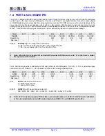
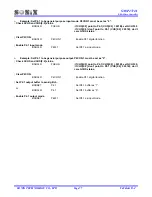
Example: Set P4.1 to be general purpose input mode. P4CON.1 must be set as “0”.
; Check GCHS and CHS[2:0] status.
B0BCLR
FGCHS
;If CHS[2:0] point to P4.1 (CHS[2:0] = 001B), set GCHS=0
;If CHS[2:0] don’t point to P4.1 (CHS[2:0]
≠
001B), don’t
care GCHS status.
; Clear P4CON.
B0BCLR
P4CON.1
; Enable P4.1 digital function.
; Enable P4.1 input mode.
B0BCLR
P4M.1
; Set P4.1 as input mode.
¾
Example: Set P4.1 to be general purpose output. P4CON.1 must be set as “0”.
; Check GCHS and CHS[2:0] status.
B0BCLR
FGCHS
;If CHS[2:0] point to P4.1 (CHS[2:0] = 001B), set GCHS=0.
;If CHS[2:0] don’t point to P4.1 (CHS[2:0]
≠
001B), don’t
care GCHS status.
; Clear P4CON.
B0BCLR
P4CON.1
; Enable P4.1 digital function.
; Set P4.1 output buffer to avoid glitch.
B0BSET
P4.1
; Set P4.1 buffer as “1”.
; or
B0BCLR
P4.1
; Set P4.1 buffer as “0”.
; Enable P4.1 output mode.
B0BSET
P4M.1
; Set P4.1 as input mode.

