SN8P2711A
8-Bit Micro-Controller
SONiX TECHNOLOGY CO., LTD
Page 110
Version 0.1
9.8 ADC
ROUTINE
EXAMPLE
¾
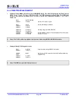
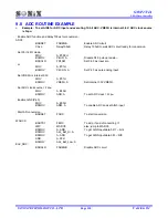
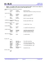
Example : To set AIN0 for ADC input and executing 12-bit ADC. VREFH is internal 3.0V. ADC clock source
is Fcpu.
; Enable ADC function and delay 100us for conversion.
ADC0:
B0BSET
FADENB
; Enable ADC circuit
CALL
Delay100uS
; Delay 100uS to wait ADC circuit ready for conversion.
; Set Port 4 I/O mode.
MOV
A,
#0FEH
B0MOV
P4UR, A
; Disable P4.0 pull-up resistor.
B0BCLR
FP40M
; Set P4.0 as input pin.
; or
MOV
A,
#01H
B0MOV
P4CON, A
; Set P4.0 as pure analog input.
; Set VREFH is internal 3.0V.
MOV
A,
#01H
B0MOV
VREFH, A
; Set internal 3.0V VREFH.
; Set ADC clock source = Fcpu.
MOV
A,
#40H
B0MOV
ADR, A
; To set ADC clock = Fcpu.
; Enable AIN0 (P4.0).
MOV
A,
#90H
B0MOV
ADM, A
; To enable ADC and set AIN0 input
; Start AD conversion.
B0BSET
FADS
; To start conversion
WADC0:
B0BTS1
FEOC
; To skip, if end of converting =1
JMP
WADC0
; else, jump to WADC0
B0MOV
A, ADB
; To get AIN0 input data bit11 ~ bit4
B0MOV
Adc_Buf_Hi,
A
B0MOV
A, ADR
; To get AIN0 input data bit3 ~ bit0
AND
A,
0FH
B0MOV
Adc_Buf_Low,
A
End_ADC:
.
B0BCLR
FADENB
; Disable ADC circuit

