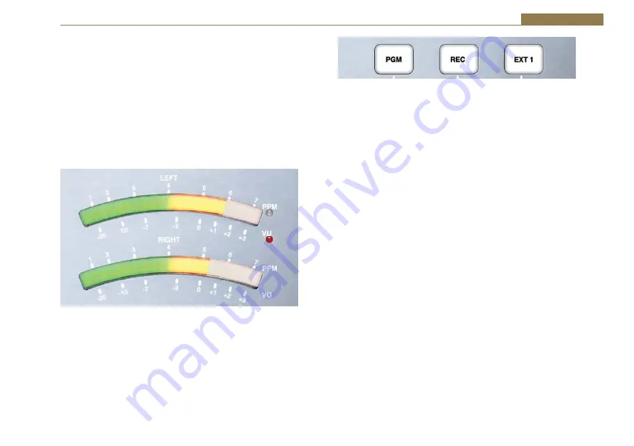
Sonifex S0 v2 Handbook Download Page 25

15

User Guide       2

LED Meter Display

The LED Meters give a visual representation of the audio routed to the 
presenter headphones including CUE/PFL and SPLIT CUE/PFL signals. They 
can be configured to display either PPM or VU. The PPM meters have a 
1-7 scale and are configured such that a 1 kHz signal, at 0dBu at the PGM 
output, will indicate a meter reading of 4. Each mark on the PPM scale 
indicates a 4 dB change in signal level. The VU meter operates between -20 
and +3 volume units and follows the standard definition for a VU meter.  A 
red LED indicates which scale is currently selected. To change scale, ensure 
all faders are closed, press and hold the PGM button and then press the EXT 
1 button.

Fig 2-15:  LED Meter Display.

PGM, REC & EXT 1 Buttons

These buttons select the source for the monitoring section of the S0 v2. 
The selected source will be routed to the monitor output and the presenter 
and guest headphones. These buttons do not affect the signals on the 
Main Program and Record outputs. The PGM button illuminates green, the 
REC button illuminates red and the EXT 1 button illuminates amber when 
selected. One button is selected at all times.

Fig 2-16: PGM, REC and EXT 1 Buttons.

Monitor, Presenter & Guest Level Controls

These controls independently adjust the volume of the signals sent to the 
loudspeaker monitor, presenter and guest headphones. The presenter and 
guest outputs are protected by a level limiter that restricts the audio level 
fed to the headphones.

Monitor AUTO CUE/PFL Button

When this button is selected, the normal output fed to the monitor 
loudspeaker will be replaced if one or more input channels have CUE PFL 
selected. The channels with CUE/PFL selected will be mixed and fed to 
this output without having to have the fader open. This button illuminates 
green when selected.

Monitor MUTE Indicator

This indicator illuminates to show when the monitor loudspeaker output 
has been automatically muted due to one of the microphone channels 
being open and routed to the PGM or REC bus. The LIGHT CONTROL output 
on the rear panel gives the option to use an external indicator to show 
when the monitor loudspeaker is muted, i.e. when a microphone output is 
active.

AUX INPUT CHANNEL 9

This stereo unbalanced 3.5mm jack socket is the auxiliary input to channel 
9. It has 10dB of gain at the input and is designed to connect directly to 
consumer level equipment. This input is in addition to the primary auxiliary 
input on the rear panel.

Summary of Contents for S0 v2

Page 1: ...Manufacturers of audio video products for radio TV broadcasters S0 v2 Radio Broadcast Mixer HANDBOOK...

Page 2: ...e for any loss or damage whatsoever arising from the use of information or any error contained in this manual No part of this manual may be reproduced or transmitted in any form or by any means electr...

Page 3: ...no Balanced Mic Stereo Unbalanced Line inputs 6 MIC INPUT 6 MIC TRIM 6 LINE INPUT 6 REMOTE OUTPUT 6 MIC LINE Button 6 PGM Button 6 REC Button 7 TRIM Control 7 PAN BAL Control 7 CUE PFL Button 7 FADER...

Page 4: ...n For S0 v2 28 7 Appendix 1 S0 v2 USB Serial Command Set 30 8 S0 v2 Skype Modification 34 Overview 34 Tools Required 34 Procedure 34 To disable Skype mode 39 Figures Fig 1 1 S0 v2 Mixer Top View 1 Fig...

Page 5: ...ernet www sonifex co uk Register Online for an Extended 2 Year Warranty As standard Sonifex products are supplied with a 1 year back to base warranty If you register the product online you can increas...

Page 6: ...duct has been registered at the Sonifex website when the Warranty Term is 24 months from the date of despatch the Contract means the quotation these Conditions of Sale and any other document incorpora...

Page 7: ...uest and expense of the Purchaser the Company will test the Goods to ascertain performance levels and provide a report of the results of that test The report will be accurate at the time of the test t...

Page 8: ...you require a different power lead please let us know when ordering the product Repairs Returns Please contact Sonifex or your supplier if you have any problems with your Sonifex product Email techni...

Page 9: ...ent a possible fire hazard under equipment fault conditions The active fuse is fitted on the outside rear panel of the unit Power Cable Connection An IEC power connector is supplied with the product w...

Page 10: ...waste All products manufactured by Sonifex Ltd have the WEEE directive label placed on the case Sonifex Ltd will be happy to give you information about local organisations that can reprocess the produ...

Page 11: ...ls and a 3 5mm stereo jack for plugging in an mp3 player The addition of a USB port allows for recording to a PC and for playing a PC automation system directly through the mixer The headphone outputs...

Page 12: ...iter Remote outputs on each channel to control external equipment such as CD players Automatic muting of the monitor output when a microphone channel is open Switching output to control external micro...

Page 13: ...AN BAL ance control is available to facilitate stereo imaging The use of VCAs controlled by the ALPS long throw 100mm faders gives a smooth repeatable response and ensures tight stereo tracking while...

Page 14: ...r REC bus and the fader is opened or closed The remotes can be set up to be either pulsed or continuous latched outputs and if in pulsed mode the START button has the capability to produce repeated st...

Page 15: ...Dimensions and Cut Out Size for Flush Mounting External dimensions 483mm W x 356mm D x 125mm H The cut out size is for reference only and should be checked with your mixer Fig 1 2 S0 v2 Mixer Cut out...

Page 16: ...ef 50dBu input and allows a wide range of microphone types to be used LINE INPUT This stereo unbalanced RCA phono is the line input to the channel It has 10dB of gain at the input and is designed to c...

Page 17: ...he right channel is turned off Turning the Fig 2 3 Mic Line Channel Strip control fully clockwise pans the signal to the right by increasing the level by 3dB The signal on the left channel is turned o...

Page 18: ...rently Fig 2 4 Channel 1 FADER Control START Button routed to the PGM or REC bus so the remote start and stop outputs are inactive Illuminated Red The remote outputs are enabled the channel is routed...

Page 19: ...ated green to indicate the channel is active on the Program Bus This button can be disabled via the Configuration Options so that it is permanently on or off Fig 2 6 Dual Stereo Channel Input Bus Sele...

Page 20: ...uminated Red The remote outputs are enabled the channel is routed to the PGM or REC bus and the fader is closed If the fader is opened the remote start output will become active and give a momentary p...

Page 21: ...o control external equipment such as starting a CD player when the channel is in AUX mode There are 2 separate signals remote start and remote stop which are both open collector outputs These signals...

Page 22: ...el is turned off Fig 2 11 Channel 9 Strip In AUX mode the control acts as BAL balance and is used to alter the stereo image of the stereo input With the control in the centre position the signal is un...

Page 23: ...in AUX mode the button indicates the state of the channel and also controls the operation of the remote outputs as follows Off The remote outputs as disabled Pressing the button will enable disable th...

Page 24: ...nch socket is the feed to the guest headphones It is wired in parallel with the guest headphone connector on the front panel of the mixer H PHONE LIMIT Control This small multi turn screw adjuster set...

Page 25: ...selected at all times Fig 2 16 PGM REC and EXT 1 Buttons Monitor Presenter Guest Level Controls These controls independently adjust the volume of the signals sent to the loudspeaker monitor presenter...

Page 26: ...r headphones It is wired in parallel with the presenter headphone connector on the rear panel of the mixer Guest AUTO CUE PFL Button When this button is selected the normal output fed to the guest s h...

Page 27: ...minate the call close the fader on channel 9 and press the LINE HOLD button to disconnect the mixer from the telephone line Receiving A Telephone Call and Routing It Through The S0 v2 1 When a telepho...

Page 28: ...red and the buttons can be released To change the current page press the Guest TALKBACK button The LED meters display will indicate the new page on the PPM scale To Exit Setup Mode 1 Press and hold th...

Page 29: ...s is set using the CUE PFL TALKBACK button Mode 1 Cleanfeed is muted when CUE PFL TALKBACK is active default Mode 2 Cleanfeed level is reduced when CUE PFL TALKBACK is active USB Audio Input CUE PFL M...

Page 30: ...el or LINE HOLD is inactive Mode 2 Momentary remote start for 0 5 seconds when the channel becomes active Additional momentary remote starts for 0 5 seconds each can be activated by pressing the START...

Page 31: ...time Using SCi For The First Time Once the S0 v2 Mixer is connected to the computer launch the SCi program The first thing to appear is the SCi Launcher which shows a list of current devices which ini...

Page 32: ...tab shows the Channel Configuration options The settings are shown individually for each of the 9 input channels and set the input and button modes and the remotes operation To change the settings on...

Page 33: ...point by pressing the Reload Settings button Any changes made since the settings were last reloaded or saved will be lost The last tab Info Updates allows the current configuration settings in SCI to...

Page 34: ...When the update is complete the S0 v2 will automatically reboot and SCi will reconnect and show the new firmware version number The S0 v2 is designed to power up in the same state it was in when powe...

Page 35: ...25 Configuration Options 3 Reset Switch Fig 3 5 Reset Switch...

Page 36: ...the USB Audio output is encoded from the audio signal on the PGM bus This involves changing 2 jumper settings that are located on the PCB directly under the front panel on the S0 v2 Contact Sonifex T...

Page 37: ...3 Pin Connectors RCA Phono Connectors This connector is used on the LINE AUX Rear and EXT1 inputs and the REC output Stereo Left Right Inputs and Outputs Inner Hot In Phase Signal Outer Ground Screen...

Page 38: ...ion 0 015 at 1kHz 0 015 at 10kHz ref 8dBu Balance Range 6dB Outputs Audio Specification Output Impedance W D Z D Maximum Output PGM output 26dBu balancedREC output Level 16dBu unbalanced Input Output...

Page 39: ...ating Anti surge fuse 2A 20 x 5mm Equipment Type S0 v2 S0 v2 radio broadcast mixer Physical Specification Dimensions Raw 48 3cm W x 35 6cm D x 12 5cm H 19 W x 14 D x 4 9 H Dimensions Boxed 67cm W x 44...

Page 40: ...l identifier 1 9 ss channel status 0 3Fh channel status bits 1 0 input selected 0 input1 1 input2 2 input3 bit 2 PGM bus state 0 off 1 on bit 3 REC bus state 0 off 1 on bit 4 PFL bus state 0 off 1 on...

Page 41: ...ld not be completed or the parameters are out of range where c channel identifier 1 9 p PFL control 0 off 1 on Select START on a channel Line Hold for channel 9 if input 1 is selected d Zd Command to...

Page 42: ...e s SPLIT PFL control 0 off 1 on Select AUTO PFL for the guest headphone output Enables disables AUTO PFL on the guests headphones Command to S0 v2 Response from S0 v2 RGAP a ACK if the command was su...

Page 43: ...lected notification Signal channels REC has been selected Command from S0 v2 9z where z channel number 1 9 Z Signal channels REC has been deselected Command from S0 v2 az where z channel number 1 9 PF...

Page 44: ...pre fade listen PFL for a playout system The upgrade gives you a third option allowing the cleanfeed output from the telco channel to be routed to a PC via the USB Setting both the microphone and spe...

Page 45: ...le for selection on channel 5 instead of channel 9 3 Locate jumpers J22 J23 and J24 Reposition the two shorting links to the configuration shown below use tweezers if necessary 5 Remove the daisy chai...

Page 46: ...sonifex co uk technical software sci setup exe Power up the S0 v2 mixer and connect a USB cable from your PC to the Serial socket on the desk If your device still does not appear click Discover Device...

Page 47: ...right After clicking Update you should now be able to browse the Firmware file on your PC Firmware files are available to download from our website If you haven not already done so download and Unzip...

Page 48: ...ble Skype mode The LED meter should perform a single sweep to indicate Skype mode is being applied and will perform a double sweep to confirm that Skype mode is enabled 10 The S0 v2 can now be connect...

Page 49: ...microphone to one of the microphone inputs and set the fader for that channel fully up Set input 9 to Aux Input 2 mode press the top button until it turns amber and set the channel 9 fader fully up I...

Page 50: ...Notes...

Page 51: ...Notes...

Page 52: ...www sonifex co uk t 44 0 1933 650 700 f 44 0 1933 650 726 sales sonifex co uk...

Reviews: