


14
2 User Guide
RECORD OUTPUT
The record output provides an independent mix that would typically be used
as a record source for jingles, program content and pre-recorded interviews.
All input channels that have the REC bus selected and the fader open will
be mixed onto this stereo unbalanced RCA (phono) output. By default, the
content of the record output is also routed to the USB Audio output channel.
This can be changed so that the program output audio is routed to the USB
Audio output channel. See the USB Audio section on “4. USB Audio” on page
26 for more details.
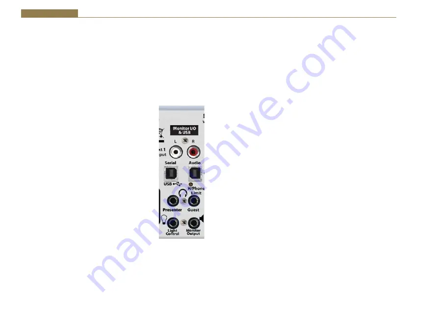
S0 v2 Monitor I/O & USB Channels
MONITOR OUTPUT
This stereo unbalanced 6.35mm (¼”) socket output is
typically used to feed the studio monitor speakers. This
output is automatically muted if a microphone channel
is routed to the PGM or REC bus and the fader is open.
This is to stop unwanted feedback. A suitable external
amplifier is required to drive the loudspeakers from
this output. Alternatively, active loudspeakers can be
connected directly.
LIGHT CONTROL
This 6.35mm (¼ inch) socket provides a switching
contact to allow an external “MIC LIVE” indicator to be
controlled. The connector provides a normally open
switch between the Tip and Sleeve, and a normally
closed switch between the Ring and the Sleeve. The
switch is activated when a microphone channel is routed
to the PGM or REC bus and the fader is open.
PRESENTER Headphones
This stereo 6.35mm (¼”) socket is the feed to the presenter headphones. It is
wired in parallel with the presenter headphone connector on the front panel
of the mixer.
Fig 2-14: MONITOR
I/O & USB.
GUEST Headphones
This Stereo 6.35mm (¼ inch) socket is the feed to the guest headphones. It is
wired in parallel with the guest headphone connector on the front panel of the
mixer.
H/PHONE LIMIT Control
This small multi turn screw adjuster sets the maximum audio level of the
signal fed to the presenter and guest headphones. It is designed to protect the
headphone users from excessive audio levels. Once the audio level exceeds
the limit threshold, the audio feed to the headphones remains at the limit
level. When the limiter is active, the audio may become distorted. If this
happens either reduce the audio level of the headphone signal or increase the
headphone limit level.
Note:
This limiter has been added to protect the hearing
of the users of this mixer, so please use the H/PHONE LIMIT control sensibly.
USB AUDIO
This USB Type B connector is the bi-directional USB Audio port that provides a
USB Audio output of the signal on the REC or PGM bus, and can accept a USB
Audio input which is routed to channels 5-8. The USB Audio input signal can
also be routed automatically to the CUE/PFL bus allowing the audio to be heard
in any on the monitor channels that have the AUTO CUE/PFL selected. This
setting is part of the configuration options. See the USB Audio section on “4.
USB Audio” on page 26 for more details.
USB SERIAL
This USB Type B connector provides the USB Serial port to allow the S0 v2 to
be connected to a PC. Using this connection, the Configuration Options can
be modified using the Sonifex SCi software. Full details of all the configuration
options and their default settings can be found in the Configuration Options
section on “3. Configuration Options” on page 18.
EXT 1 INPUT
These stereo unbalanced RCA phonos provides an external input that would
typically be used to monitor the on-air or post-processor output to ensure it is
correct.


