


13
EN
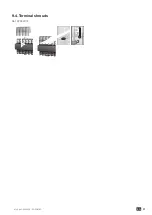
ATyS p M - 542935E - SOCOMEC
STEP 5
Programming
Check
STEP 4
Whilst in manual mode, check the wiring and if ok power
up the product.
Product programming
Programming access is possible in Automatic mode, when the product is in position I with source 1
available, and in Manual mode in any position and with at least one available source.
Note
: For complete programming details: download the instruction manual from the Socomec website.
STEP 6A
Automatic
operation
Close the front cover as
shown to put the product
into automatic mode.
STEP 6B
Manual operation
• Open the front cover as
shown to put into manual
mode.
• Use the handle situated in
the front panel under the cover to operate the
transfer switch.
• Check the changeover switch position on the
indicator before operating.
To simplify operation
use the handle with the
extension provided.
(Max 8 Nm)
II
I
o
0,5 to 2,5 mm
2
#28 to #14 AWG
0,5 to 2,5 mm
2
#28 to #14 AWG
6 mm / 0,236"
Slotted head 2,5 mm
90º
90º
Extension
STEP 6C
Padlocking mode
• In order to padlock put the
product in manual mode.
• Pull the locking mecha-
nism and insert a padlock
as shown.
• As standard padlocking in the 0 position.
Configurable to I-0-II (see step 1).
1x 4-8 mm
To access programming
Default code: 1000
Browsing
1
2
1
2
Press for 3 s
1
2
2
1
To modify the
value of this
digit
1
2
1
2
1
2
To access the
other digits
1
2
1
2
Validate entry
Exit programming
1
2
Press the validate
button for
3 seconds.
TIMERS
Setting range
Defaut Value
1FT
Loss of source 1 Validation timer.
0 to 60 sec
(1)
3 sec
1RT
Source 1 return validation timer.
0 to 3600 sec
180 sec
2FT
Loss of source 2 Validation timer.
0 to 60 sec
3 sec
2RT
Source 2 return validation timer.
0 to 3600 sec
5 sec
2AT
Standby network stability validation before transfer
0 to 3600 sec
5 sec
2CT
Run on timer.
0 to 600 sec
180 sec
ODT
Dead band timer.
0 to 20 sec
3 sec
Parameters
Setting range
Default value
NEUTRAL
Neutral position on the switch
AUTO: neutral position is automaticaly detected when the product is supplied
the first time.
LEFT: neutral must be connected to the left that means on the terminal 1 from
each switch.
RIGHT: neutral must be connected to the right that means on the terminal 7 from
each switch.
AUTO
LEFT
RIGHT
AUTO
NOM. VOLT.
Nominal voltage
Phase/phase or phase/neutral in 1BL and 41NBL
From 180 to 480 Vac
400Vac (230/400V version)
230Vac (127/230V version)
NOM. FREQ.
Nominal Frequency
50 or 60Hz
50Hz
APP
Type of application
M-G: network - Genset
M-M: network - network
M-G
M-M
M-G
RETRANS
Retransfer inhibit feature, press on Validation button required to allow retransfer
form Gen to Main
YES or NO
NO
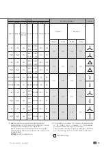
NETWORK
Network configuration*
3NBL / 4NBL / 41NBL / 1BL
(230/400V version)
4NBL / 3NBL / 2NBL / 42NBL
(127/230V version)
4NBL
(1) O to 3600 secs in M-M network
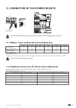
* The wiring must be adapted to the network configuration. Below, the main configuration types.
3 phase / 4 wire
3 phase / 3 wire
2 phase / 3 wire
2 phase / 2 wire
1 phase / 2 wire
4NBL
4BL
1
3
2
N
3NBL
3BL
L1
L3
L2
NM
2NBL
1
2
3
2BL
1
3
1BL
1
N
1
2
1
2
1
2
1
2
1
2
1
2
1
2
1
2
1
2
1
2
1
2
1
2
1
2
1
2
1
2
1
2
1
2
1
2
1
2
1
2
1
2
1
2
1
2
1
2
1
2
1
2
1
2
1
2
1
2
1
2
1
2
1
2
1
2
1
2
1
2
(9)
(9)
(9)
1
2
1
2
1
2
1
2
1
2
1
2
1
2
1
2
1
2
1
2
1
2
1
2
1
2
1
2
1
2
1
2
1
2
1
2
1
2
1
2
1
2
1
2
1
2
1
2
1
2
1
2
1
2
1
2
1
2
1
2
2
1
1
2
1
2
1
2
1
2
1
2
1
2
1
2
1
2
1
2
1
2
1
2
1
2
1
2
(1)
(7)
(1)
(1)
(3)
(3)
(3)
(4)
(4)
1
2
(4)
(6)
1
2
(1)
(3)
(2)
(2)
(8)
(1)
(1)
(8)
(1)
(5)
(5)
(5)
(5)
(5)
1
2
Configure
parameters
Configure voltage
thresholds and
hysteresis
Frequency thresholds
and hysteresis
configuration
Timer configuration
Input - output
configuration
Communication
configuration
(1) Only accessible if the Setup menu variable “APP” is at “M-G”,
see Setup Menu
(2) Only accessible if the Setup menu variable “APP” is at “M-M”,
see Setup Menu
(3) Only accessible if one of the inputs is EON, see I/O Menu
(4) Only accessible if one of the inputs is EOF, see I/O Menu
(5) Only on the COMM version, see description in the option section
(6) Only accessible if one of the outputs is LSC, see I/O Menu
(7) Default values: 230V for version 127/230 400V for version
230/400
(8) only accessible when the “RETURN O” variable in the Setup menu
is set to “YES”, see SETUP menu.
(9) Only accessible if the associated input is configured.
* UNL = Unlimited
The entry point for programming mode is the SETUP menu.
1
2
Parameters must always be adjusted and verified for
compliance with the application.
The default values are loaded as standard.


