background image


16

 - 


4. List of Parameters for each Mode 

These parameters require configuration in each control mode. Please configure parameters as required. 
Refer to 

“LECSA Operation Manual (Simplified Edition)”, section 5.3 and “LECSA Operation Manual”, chapter 4 

for details. 
Refe

r to “LECSA Operation Manual”, chapter 4 for parameters which are not disclosed in this document. 


Setup software 

(MR Configurator2

TM 

: LEC-MRC2E) is necessary for the setting of parameter. 

*1 Setup software version 1.52E or above is required. 
*2 The setup software (MR Configurator2

TM 

: LEC-MRC2E) must be purchased as an additional item. 

*3 The USB cable (LEC-MR-J3USB) must be purchased as an additional item. 


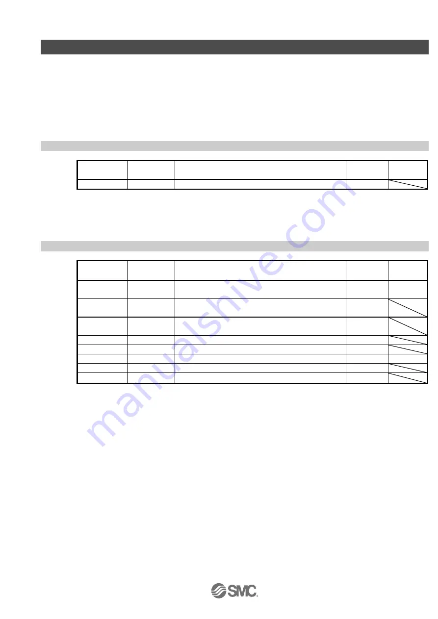
4.1 Parameters common to each mode 

(1) [Basic settings parameters (No.PA

□□)] 

No. 

Symbol 

Name 

Initial value 

Unit 

PA01 

*STY 

Control mode   

000h 


  (2) [I/O setting parameters (No. PD

□□

)] 

These parameters are set when changing the input/output signal assignment and switching the input signal 
automatic  on.  See 

“LECSA  Operation  Manual  (Simplified  Edition)”,  section  5.5  and  “LECSA  Operation 

Manual” section 4.4 for details. 


4.2 Position control mode 

(1) [Basic settings parameters (No.PA

□□)]


No. 

Symbol 

Description 

Initial value 

Unit 

PA05 

*FBP 

Number of command input pulses per revolution 

100 

×100 

pulse/rev 

PA06 

CMX 

Electronic gear numerator 

  (Command input pulse multiplying factor numerator)   


PA07 

CDV 

Electronic gear denominator 

  (Command input pulse multiplying factor denominator)   


PA08 

ATU 

Auto tuning mode 

001h 


PA09 

RSP 

Auto tuning response 


PA10 

INP 

In-position range 

100 

pulse 

PA13 

*PLSS 

Command input pulse form 

000h 


PA14 

*POL 

Rotation direction selection 


Summary of Contents for LECSA Series

Page 1: ...PRODUCT NAME AC Servo Motor Driver Pulse input type Positioning type MODEL Series Product Number LECSA Series Simplified Edition LEC OM05611 Doc No JXC OMT0052 A...

Page 2: ...No No No No JXC OMT0052 LEC OM05610 JXC OMT0052 A LEC OM05611...

Page 3: ...software MR Configurator2TM 19 5 1 1 Installation Method 19 5 2 Basic driver set up for Initial Test Drive 19 5 2 1 Start up the Setup software MR Configurator2TM 20 5 2 2 System Settings 21 5 2 3 Mod...

Page 4: ...Saving Loading Project 65 5 9 1 Saving Project 65 5 9 2 To Load saved Project 66 5 10 Saving Loading Point table 67 5 10 1 Saving Point table 67 5 10 2 To Load saved Point table 68 5 11 Acquisition of...

Page 5: ...3 8 Troubleshooting 91 8 1 Alarms and Warning List 91 8 2 Alarm Display 93...

Page 6: ...Only personnel with appropriate training should operate machinery and equipment The product specified here may become unsafe if handled incorrectly The assembly operation and maintenance of machines...

Page 7: ...tance or replacement parts Please consult your nearest sales branch For any failure or damage reported within the warranty period which is clearly our responsibility a replacement product or necessary...

Page 8: ...ning Positioning mode Point table Set the positioning data rotation speed Acceleration Deceleration time constant of the drivers point table and execute ON OFF control of the positioning operation usi...

Page 9: ...e position return Method Position Control Mode Configuration See 7 1 Position Control Mode Pulse input Positioning mode Configuration See 7 4 Positioning mode Point table method See 7 5 Positioning Mo...

Page 10: ...orced stop Note 5 Servo on RA OFF Trouble MC ON MC SK Note 5 Forced stop Note 6 Circuit protector Note 4 Note 2 Note 3 Note 3 24VDC Note 7 Note 1 Built in regenerative resistor 1 Power supply input te...

Page 11: ...Note 10 11 Note 9 Servo on Reset 10m max Note 1 USB cable option MR Configurator CN3 Personal computer Note 14 Note 15 Servo amplifier 10m max 2m max Note 8 Note 7 Programmable logic controller FX3U M...

Page 12: ...opped suddenly and servo lock is enabled LSN Reverse rotation stroke end Turn this signal on before operation When this signal turns off the product is stopped suddenly and servo lock is enabled TL1 I...

Page 13: ...In position This signal turns on when the droop pulse is within the setting range SA Speed reached When the servo motor rotation speed reaches the set speed this signal turns on VLC Limiting speed Thi...

Page 14: ...er Control common Encoder Z phase pulse open collector Encoder Z phase pulse differential line driver 19 20 LZR CN1 1 13 DICOM DOCOM 10m max USB cable option CN3 MR Configurator Personal computer 24VD...

Page 15: ...ntrol common Encoder Z phase pulse open collector CN1 Ready Encoder Z phase pulse differential line driver 19 LZ LZR Note 6 CN1 1 13 DICOM DOCOM Personal computer USB cable option CN3 10m max Note 7 M...

Page 16: ...er 19 20 LZR Note 7 CN1 1 13 DICOM DOCOM 10m max CN3 Note 8 MR Configurator Personal computer 24VDC RA1 RA2 RA3 RA4 Note 4 9 Note 9 11 8 4 3 7 Forced stop Servo on Automatic manual selection Forward r...

Page 17: ...c Servo amplifier Switch Approx 5mA DICOM VCES 1 0V ICEO 100 A 24VDC 10 200mA Approx 5 6k 2 Digital output interface DO 1 A maximum voltage drop of 2 6V may occur in the driver Note 24VDC 10 2 00mA If...

Page 18: ...Basic settings parameters No PA No Symbol Name Initial value Unit PA01 STY Control mode 000h 2 I O setting parameters No PD These parameters are set when changing the input output signal assignment a...

Page 19: ...d 4 Applied 200 r min PC32 SC5 Internal speed command 5 Applied 300 r min PC33 SC6 Internal speed command 6 Applied 500 r min PC34 SC7 Internal speed command 7 Applied 800 r min 4 4 Torque control mod...

Page 20: ...e Initial value Unit PE01 CTY Command mode selection 0000h PE02 FTY Feeding function selection 0000h PE03 ZTY Home position return type 0010h PE04 ZRF Home position return speed 500 r min PE06 ZST Hom...

Page 21: ...setup software MR Configurator2TM LEC MRC2E must be purchased as an additional item 3 The USB cable LEC MR J3USB must be purchased as an additional item 5 1 1 Installation Method Perform installation...

Page 22: ...up the Setup software MR Configurator2TM Connect the PC and LECSA using the USB cable Turn on the power of the LECSA Start application MR Configurator2 Once the application starts the screen below wi...

Page 23: ...to change parameter PC40 to 0 The default value of parameter PC40 is 0 When using LECSA for the first time please use the default parameter for PC40 as 0 Please select servo amplifier connection USB...

Page 24: ...n Is the PC and LECSA amplifier connected with the USB cable Is the USB driver installed Is the USB driver which is compliant to Windows version installed Is parameter PC40 set to 0 PC40 is a paramete...

Page 25: ...J3USB must be purchased as an additional item From the Parameter menu select Parameter Setting the parameter setting window will open The explanation of the parameter item is displayed in MR2 Help Whe...

Page 26: ...o not cycle the power it does not register the data in the driver Note2 Selected Items Write It writes the parameter values of the corresponding frame to the driver Single Axis Write Writes all of the...

Page 27: ...control mode pulse input Set the parameters of the PA01 to 000 in the Basic tab Setting example of the Control mode PA01 in the case of setting to Positioning Point table Set the parameters of the PA0...

Page 28: ...Home position return position data m PE08 0 2000 1000 stroke 200 1000 stroke Stopper type home position return stopper time msec PE10 100 200 Stopper type home position return torque limit value PE11...

Page 29: ...home position return torque limit value PE11 15 30 Regenerative option PA02 000 000 Non 002 LEC MR RB 032 Rotation direction selection PA14 0 1 Counter motors side 0 Counter motors side 1 Counter mot...

Page 30: ...1000 stroke Stopper type home position return stopper time msec PE10 100 200 Stopper type home position return torque limit value PE11 15 30 Regenerative option PA02 000 000 Non 002 LEC MR RB 032 003...

Page 31: ...me position return stopper time msec PE10 100 200 Stopper type home position return torque limit value PE11 15 30 Regenerative option PA02 000 000 Non 002 LEC MR RB 032 Rotation direction selection 4...

Page 32: ...0 100 200 Stopper type home position return torque limit value PE11 15 30 Regenerative option PA02 000 000 Non 002 LEC MR RB 032 003 LEC MR RB 12 Rotation direction selection 4 PA14 0 0 Counter motors...

Page 33: ...multiplying factor numerator 1 1 to 65535 PA07 CDV Electronic gear denominator Command pulse multiplying factor denominator 1 1 to 65535 1 Complete configuration as shown below Ex Travel amount per 1...

Page 34: ...parameter in the Basic tab of the List display also changes to 000 To use positioning mode point table navigate to the Basic tab of the Parameter Setting screen Control mode selection Please select P...

Page 35: ...tion Internal speed Internal torque PA13 PLSS Command input pulse form 000h Refer to the text Select the input form of the pulse train input signal Command pulses may be input in any of three differen...

Page 36: ...34 Set the PA13 to 201 in the Basic tab Click on the Single Axis Write button Turn the power OFF and ON again Parameter is enabled...

Page 37: ...parameter perform Verify Click the Verify button on the Parameter Setting window Verfication Setting screen will display Please select the comparison target Amplifier Compare with the parameters set...

Page 38: ...ter storage method Click the Set To Default button on the Parameter Setting window Please click Yes button Parameter Block screen will display Set the default using an editable parameter as the browsa...

Page 39: ...isplayed by selecting Jog Mode from the Test Mode menu in the setup software Click OK When using this function all external input signal operation will be diabled If controlling using a PLC or other u...

Page 40: ...the rotation direction of the actuator does not change if you change the setting of parameter PA14 Rotation direction selection The actuator moves in the direction of Forward CCW button and Reverse CW...

Page 41: ...Input signal automatic ON selection settings defines which input signals will turn ON automatically when the control circuit power supplyis turned on doing this allows additional I O signal selection...

Page 42: ...positioning mode point table congifure the operation mode using automatic manual selection MD0 The MD0 off selection will allow Jog operation and it will require an input reserved for MD0 For Automati...

Page 43: ...ion 13 2 3 for details regarding signals See LECSA Operation Manual section 4 4 2 for details on parameter setting values Pins CN1 23 and CN1 25 can be allocated in current Sink NPN interface interfac...

Page 44: ...tup Software The Parameter Setting window will be displayed when parameter list is selected from the parameters menu in the setup software Click the I O tab When changing the allocation of signals par...

Page 45: ...43 5 5 4 Allocation Examples for Position Control Mode Pulse Input 1 Example of Gain switch CDP Settings When changing pin CN1 4 from Servo on SON to Gain switch CDP Changing PD05 from 0202 to 0211 1...

Page 46: ...ick on the Single Axis Write button Cycle the power off then on for the parametersto be enabled Please allocate pins CN1 4 separately See LECSA Operation Manual section 4 4 2 for details on allocation...

Page 47: ...he default allocation allocates signals DI0 to CN1 5 and DI1 to CN1 23 Note CN1 23 can only be used if the input is configured as current sink NPN 8 points can be specified however 1 point is reserved...

Page 48: ...7 Points in current SINK NPN Interface Changing pin CN1 7 from Reverse rotation start ST2 to point table no program no selection 3 DI2 Change PD12 from 0808 to 2E08 Note CN1 23 can only be used if the...

Page 49: ...tion MD0 to point table no program no selection 3 DI2 Changing pins CN1 7 from Reverse rotation start ST2 to point table no program no selection 2 DI1 Change PD04 from 2003 to 2E03 Change PD12 from 08...

Page 50: ...nd then on for the parameters to be enabled Complete pin CN1 7 allocation separately See LECSA Operation Manual section 4 4 2 for details on allocation of input signals to pins CN1 3 CN1 8 See LECSA O...

Page 51: ...8 have been changed It is necessary to confirm these are correctly assigned From the Monitor menu of the Setup Software select I O Monitor The I O Monitor window opens and displays the inputs and outp...

Page 52: ...indow opens Check Command pulse unit Electronic gear valid and click OK Electronic gear ratio that is set in the PA05 PA06 PA07 is enabled Click OK When using this function external input signal opera...

Page 53: ...verse CW button Check the command impulse unit electronic gear enabled The electronic gear duty set to PA05 PA06 PA07 will be enabled See LECSA Operation Manual Simplified Edition section 5 3 4 Parame...

Page 54: ...ate if this is set to 0 If the rotation speed is too low this may cause vibration check the actuator while changing settings Movement speed mm s must be converted into rotation speed r min See below f...

Page 55: ...d for each actuator The acceleration deceleration time must be converted from the acceleration deceleration speed See below for the conversion formula Calculating Acceleration deceleration conversion...

Page 56: ...ual Simplified Edition section 5 3 4 the travel distance of the actuator per 1 pulse will be as follows Position control mode pulse input travel distance of the actuator per 1 pulse 10 m 0 01 mm Posit...

Page 57: ...nt table mode the point table target position speed data acceleration time deceleration time etc must be configured 5 7 1 Point table List Using the Positioning Data menu in the setup software The Poi...

Page 58: ...nt table in the incremental value command system 2 Automatic operation is performed in accordance with a single point table chosen 3 Operation is performed in accordance with consecutive point tables...

Page 59: ...00mm set parameter PE02 Feed function selection to 0001 and the Feed length multiplication STM Multiplier value to x10 Set the feed length multiplication STM Multiplier of target position in parameter...

Page 60: ...ngth multiplication STM Multiplier Feed unit m Target position input range mm 1 999 999 to 999 999 10 9999 99 to 9999 99 100 99999 9 to 99999 9 1000 999999 to 999999 For actuators with a stroke less t...

Page 61: ...t to a value within the stroke range If electronic gear parameters PA05 PA06 PA07 are set according to LECSA Operation Manual Simplified Edition section 5 3 4 in positioning mode The smallest unit for...

Page 62: ...elow for the conversion formula Example using a 20 mm Lead Actuator with target travel speed of 500 mm sec The rotation speed must be a value between 0 and the allowable actuator speed The actuator wi...

Page 63: ...3000 mm s2 133 ms The acceleration time constant deceleration time constant defines the time in ms when the motor rotations of 3000 min are met The acceleration time constant deceleration time constan...

Page 64: ...ct point table number Press Start The actuator will set the position at which the power was turned on as the home position 0 and move towards the defined point table position Check parameters PA05 PA0...

Page 65: ...select Save As Please specify location to be saved Please enter any file name Click Save Files Saved prm2 Settings files for parameters PA PB PC PD and PE Note Always upload current parameters from t...

Page 66: ...saved Parameters From the Parameter Setting window in the setup software select Open Please specify location of the file Please select the file you wish to import parameters prm2 Click Open Parameter...

Page 67: ...ase enter any file name Click Save Project will be saved in the specified folder If you change the drive path name it will be saved in the drive path name project name folder you have changed Note Alw...

Page 68: ...om the Project menu in the setup software select Open Please select the drive path name project name that you want to read parameters are stored Please select the file you wish to import project mrc2...

Page 69: ...67 5 10 Saving Loading Point table 5 10 1 Saving Point table From the Point Table window in the setup software select Save As Please specify location to be saved Please enter any file name Click Save...

Page 70: ...ad saved Point table From the Point table window in the setup software select Open Please specify location of the file Please select the file you wish to import point table ptb2 Click Open Point table...

Page 71: ...h graph monitor With the setup software MR Configurator2TM LEC MRC2E monitor graph function the motion waveform during electric actuator operation can be obtained as described below Click Monitor Grap...

Page 72: ...etting window to set the items to display the waveform trigger conditions and horizontal axis of the graph 3 types analogue waveforms analogue 1 to 3 and 4 types of digital waveforms digital 1 to 4 ca...

Page 73: ...are displayed Click of Level Condition to set the condition For Motor speed when the operation direction is positive Level should be100 and when the operation direction is negative Level should be 10...

Page 74: ...00 pulse The displayed number of pulses is units of the encoder pulses 100pulse 7 Droop pulse by 1 pulse The droop pulse on the deviation counter is displayed in units of 1 pulse Note Any area beyond...

Page 75: ...played in An overload alarm will occur when margin is 0 0 1 19 Excessive error alarm margin The margin until the error reaches the excessive error AL 52 alarm level is displayed in encoder pulses An e...

Page 76: ...waveforms can be captured and displayed Click the Start button every time measurement fresh capture is required The advantage of this method of capturing the waveform is a waveform will not be updated...

Page 77: ...er conditions in 5 11 1 2 are satisfied the operation waveforms can be captured When the time set in 5 11 1 1 has passed after the acquisition start the acquisition of the waveforms will complete and...

Page 78: ...ed and save the data Waveform data file extension gpf2 will be prepared If the waveform condition needs to be checked it can be displayed on the graph window Click the Save Image button Select the fol...

Page 79: ...exceed 999999999 it returns to zero Press the Clear button to reset the display value to 0 zero Reverse rotation is indicated by a minus sign 999999999 to 999999999 pulse 2 Servo motor speed The serv...

Page 80: ...isplayed in encoder pulses The value returns to 0 when it exceeds the maximum number of pulses 0 to 262143 pulse 11 Load inertia moment ratio The estimated ratio of the servo motor axis converted iner...

Page 81: ...turn method using a proximity dog Used when it is minimisation of the proximity dog length is required Data set type An arbitrary position defined as a home position No proximity dog required Stopper...

Page 82: ...DI0 DI1 and DI2 Program metho Program Select a program that has the home position return ZRT command Stopper type home position return Parameter No PE03 3 Stopper type home position return is selected...

Page 83: ...ing delays in output signal sequence from the PC or PLC and variations of a signal change due to hardware 2 TLC turns ON when the torque reaches the value set in forward torque limit parameter No PA11...

Page 84: ...After changing gain Before changing gain Change of each gain CDT 100ms 63 4 Droop pulses pulses 0 Command pulse Droop pulses CDL CDL 95ms 95ms Electromagnetic brake interlock MBR Note 1 ON ON OFF 0 r...

Page 85: ...position Connect the wirings as follows when operating in forward or reverse rotation with the internal speed command set to the eighth speed Note that the inputs are configured as Current sink NPN Ty...

Page 86: ...otation in regenerative mode 1 0 CW forward rotation in driving mode reverse rotation in regenerative mode 1 1 Torque is not generated Note 0 off 1 on Generally make connection as shown below Note tha...

Page 87: ...Note Device Selection description Point table No Program No selection 2 DI1 CN1 23 DI2 DI1 DI0 Point table method DI 1 0 0 0 Home position return mode 0 0 1 Point table No 1 0 1 0 Point table No 2 0...

Page 88: ...h match CPO Point table No Servo motor speed Forward rotation Reverse rotation 0r min ON OFF Forward rotation start ST1 1 ON OFF Note 2 Travel completion MEND Point table No output PT0 to PT2 3ms or l...

Page 89: ...ll Stop time Auxiliary functions Driver operation display U UP P D DO OW WN N When the set value is flashing it is not registered When the set value is flashing it is not registered a The set screen c...

Page 90: ...m 1 Setup software version 1 52E or above is required 2 Setup software should be prepared by the user 3 USB cable LEC MR J3USB is required for software installation See LECSA Operation Manual section...

Page 91: ...ption SPN Speed Motor speed SPN Setting value 0 to instantaneous permissible speed r min Used to set the command speed of the servo motor for positioning The set value should be equal to or less than...

Page 92: ...ogram No 5 Point table No Program No selection 3 DI2 1 0 1 Program No 6 DI 1 1 1 0 Program No 7 1 1 1 Program No 8 Note 0 off 1 on Program input 1 PI1 Turn PI1 on to resume the step stopped by the SIN...

Page 93: ...1 RAM A 13 Clock error A 15 Memory error 2 EEP ROM A 16 Encoder initial communication error1 A 17 Board error A 19 Memory error 3 Flash ROM A 1A Motor combination error A 1C Software combination error...

Page 94: ...e 2 A 99 Stroke limit warning Stops Note 2 A E0 Excessive regeneration warning Does not stop A E1 Overload warning 1 Does not stop A E6 Servo forced stop warning Stops A E9 Main circuit off warning St...

Page 95: ...tion history is listed for alarms that occurred in the past Click Diagnosis Alarm Display of the setup software to display Alarm Display window Alarms warnings currently occurring in the driver displa...

Page 96: ...4 7th printing No LEC OM05608 Apr 2015 8th printing No LEC OM05609 Sep 2015 9th printing No LEC OM05610 No JXC OMT0051 Sep 2016 10th printing No LEC OM05611 No JXC OMT0051 A Jun 2017 11th printing 4 1...

Reviews: