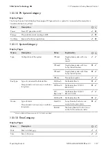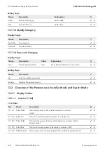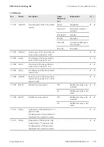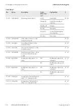
112# Device
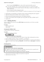
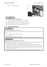
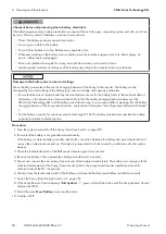
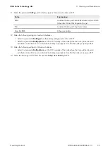
No.
Name
Description
Value
(Plain text
no.)
Explanation
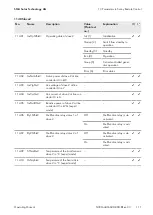
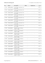
112.01
InvOpStt
Operating state of the Sunny Island
inverter
Init (1)
Initialization
✓
✓
Startup (2)
Switch from standby to
operation
Standby (3)
Standby
Run (4)
Operation
I-Loop (5)
Current-controlled gener-
ator operation
Error (6)
Error status
112.02
InvPwrAt
Active power of the Sunny Island in-
verter at line conductor L1 in kW
–
–
✓
✓
112.03
InvVtg
Grid voltage of the Sunny Island in-
verter at line conductor L1 in V
–
–
✓
✓
112.04
InvCur
Line current of the Sunny Island in-
verter at line conductor L1 in A
–
–
✓
✓
112.05
InvFrq
Grid frequency of the Sunny Island
inverter in Hz
–
–
✓
✓
112.06
InvPwrRt
Reactive power of the Sunny Island
inverter at line conductor L1 in kVAr
(expert mode)
–
–
✓
✓
112.07
Rly1Stt
Multifunction relay status 1
Off
Multifunction relay is de-
activated.
✓
✓
On
Multifunction relay is acti-
vated.
112.08
Rly2Stt
Multifunction relay status 2
Off
Multifunction relay is de-
activated.
✓
✓
On
Multifunction relay is acti-
vated.
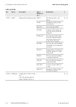
112.12
TrfTmp
Temperature of the transformer in °C
(expert mode)
The temperature of the transformer is
displayed in the master of a cluster.
–
–
✓
✓
112.13
HsTmp
Temperature of the heat sink in the
Sunny Island in °C (expert mode)
The temperature of the heat sink is
displayed in the master of a cluster.
–
–
✓
✓
13 Parameters in Sunny Remote Control
SMA Solar Technology AG
Operating Manual
109
SI30M-44M-60H-80H-BE-en-33
Summary of Contents for SUNNY ISLAND 3.0M
Page 163: ......
Page 164: ...www SMA Solar com...

