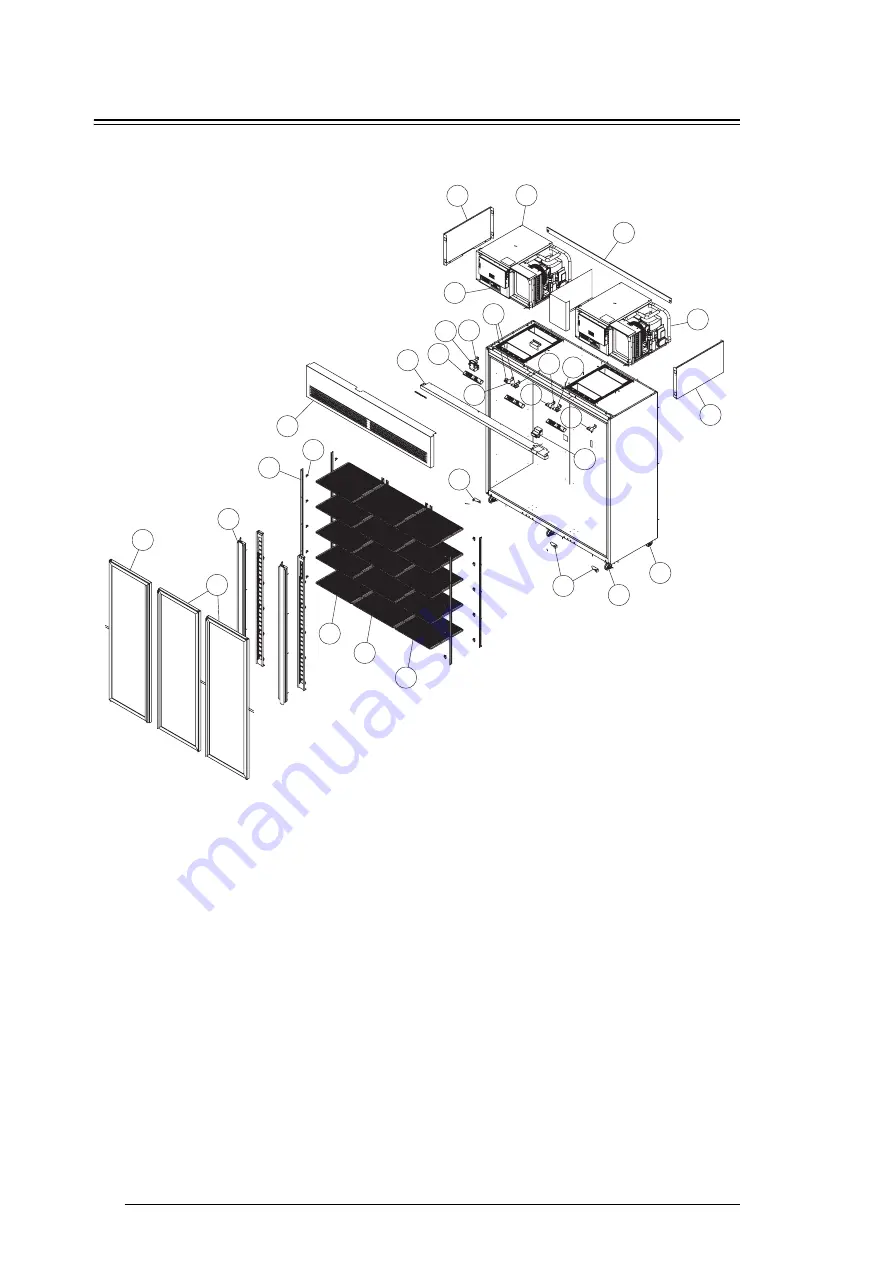
38
Spare Parts
Service Manual
SKOPE VF Series
VF1500 Series Cabinet Assembly
1
2
3
5
7
6
12
11
13
15
16
17
18
19
20
21
23
4
8
9
10
14
22
Page 1: ...VF Series SKOPE Glass Door Vertical Freezer Service Manual MAN10522 Rev 3 1 Jul 2018...
Page 2: ...e co nz Trademark Infringement The SKOPE trademark on this product is infringed if the owner for the time being does any of the following Applies the trade mark to the product after their state condit...
Page 3: ...20 Program 485 BN1 21 Program 485 BN2 23 Program 485 BN3 25 3 Wiring VF Series Single Unit EBM fan motors 28 VF Series Twin Unit EBM fan motors 29 VF Series Single Unit UNADA fan motors 30 VF Series T...
Page 4: ...Refitting 58 Hinge Reversal 59 Cabinet Electrics 60 Control Panel 60 Cabinet Fuses 60 Refrigeration Unit 61 Introduction 61 Refrigeration Unit Assembly 62 Removing the Refrigeration Unit 63 High Press...
Page 5: ...5 40 C Climatic Class 5 32 C Climatic Class 5 Cabinet temp range 18 C to 21 C 18 C to 21 C 9 C to 12 C Electrical Current draw 7 5 Amps 7 5 Amps 7 5 Amps Internal lighting 1 side light 22 Watt T8 LED...
Page 6: ...32 C Climatic Class 5 Cabinet temp range 18 C to 21 C 18 C to 21 C 9 C to 12 C Electrical Current draw 9 Amps 9 Amps 9 Amps Internal lighting 1 centre pillar light Twin 24 Watt T8 LED tube 26 1500mm...
Page 7: ...tube door switched 26 1500mm 1 centre pillar light Twin 24 Watt T8 LED tube 26 1500mm Sign lighting Not as standard Optional vented lit sign panel 1 20 Watt T8 Frosted LED tube 26 1200mm Not as standa...
Page 8: ...C 9 C to 12 C Electrical Current draw Total 14 Amps 2 10A plugs Total 14 Amps 2 10A plugs Total 14 Amps 2 10A plugs Internal lighting 2 centre pillar light Twin 24 Watt T8 LED tube 26 1500mm 2 centre...
Page 9: ...Specifications Service Manual Servicing Tools Tools required for servicing may consist of the following Screwdriver with Pozidriv PZ1 and PZ2 bit Slotted screwdriver Small slotted screwdriver for elec...
Page 10: ...controller has a built in minimum off cycle time of 5 minutes and features regular temperature terminated defrost cycles During the defrost cycle the compressor and evaporator fan switch off The SKOPE...
Page 11: ...Manual defrost down Press for more than 5 seconds to initiate manual defrost To scroll settings down in program mode 5 Compressor ON when the compressor and condenser fan starts Flashes when activatio...
Page 12: ...ng and holding the button Continuous Cycle The continuous cycle can be used to pull down the temperature of product inside the freezer quickly During a continuous cool down the compressor runs continu...
Page 13: ...rator Probe The evaporator probe measures the evaporator coil temperature The evaporator coil temperature is used for evaporator fan operation fan will start when evaporator coil temperature drops to...
Page 14: ...urned to temperature specification Flashing Product LOW temperature alarm Door open alarm Door has been open for longer than 2 minutes Flashes between cabinet temperature and dor alarm 1 Check door is...
Page 15: ...point Parameter set Operational mode Factory set point Adjsutable temperature range 485 BN1 Glass door lit integral freezer solid door unlit integral freezer 21 C 26 C to 16 C 485 BN2 Solid door lit i...
Page 16: ...connect the freezer from the power supply 2 Press and hold the key while plugging the freezer into the power supply this may require two people After a few seconds the controller is reset and program...
Page 17: ...ns Field Adjustable Programming Within each program set are field adjustable Type C parameters To assist with locating the parameters can be displayed in groups detailed in the table below Non useful...
Page 18: ...ey to display a menu that is used to quickly access the group of parameters to be modified see table on previous page 3 Scroll the menu with the or keys The display shows the codes of the various cate...
Page 19: ...he key to display the first sub parameter 11 Press the or keys to display all the sub parameters 12 Press the key to display the associated value 13 Increase or decrease the value using the or keys re...
Page 20: ...tl from 1 to 7 Parameters Only an authorised service agent should change the parameters A label on the top of the controller indicates the factory parameter program Refer to the tables below for param...
Page 21: ...penings during period rt Read only Temperature Set Point Value to alter differential by when in Night mode Enable monitoring NOT related to HACCP Elapsed monitoring time Read only Max temperature duri...
Page 22: ...of Week 11 every day Defrost 1 Start Time Hour 24hr clock High Ambient Temperature Alarm Minute of most recent event High Ambient Temperature Alarm Duration of most recent event High Temperature HACCP...
Page 23: ...door openings during period rt Read only Temperature Set Point Value to alter differential by when in Night mode Enable monitoring NOT related to HACCP Elapsed monitoring time Read only Max temperatur...
Page 24: ...Days of Week 11 every day Defrost 1 Start Time Hour 24hr clock High Ambient Temperature Alarm Minute of most recent event High Ambient Temperature Alarm Duration of most recent event High Temperature...
Page 25: ...of door openings during period rt Read only Temperature Set Point Value to alter differential by when in Night mode Enable monitoring NOT related to HACCP Elapsed monitoring time Read only Max tempera...
Page 26: ...rt Time Days of Week 11 every day Defrost 1 Start Time Hour 24hr clock High Ambient Temperature Alarm Minute of most recent event High Ambient Temperature Alarm Duration of most recent event High Temp...
Page 27: ...27 SKOPE VF Series SKOPE CAREL ir33 Controller Service Manual Notes...
Page 28: ...the relay may be de energised in an alarm state It may be prudent to latch the alarm on the BMS C NO NC Pressure Switch Pressure Switch Relay see detail A Sump Defrost Elements Not Used Compressor Con...
Page 29: ...er GNYE E N L BU T6 1 T6 2 Cabinet light 1 Sign light EMC Filter BN BU BN 11 12 Comp 2 1 3 4 CAREL ir33 Controller 15 16 17 18 19 20 13 14 AUX 1 7 6 5 AUX 2 10 8 9 AUX 3 T3 4 RD Cabinet light 2 T1 1 T...
Page 30: ...17 18 19 20 13 14 AUX 1 7 6 5 AUX 2 10 8 9 AUX 3 T3 4 RD Sign light T1 1 T1 2 T3 3 BN BN BU GNYE T3 9 RD T3 7 Pillar Facia Heater Element T3 5 T2 2 BN BU T2 1 BU BN BN BU BU BK GS Thermal Cut Out BU D...
Page 31: ...RD Cabinet light 2 T1 1 T1 2 T3 3 BN BN BU GNYE T3 9 RD T3 7 T3 5 T2 2 BN BU T2 1 BU BN BN BU BU BK GS Thermal Cut Out BU Door Switch Door Switch Door Switch OG OG OG OG T4 1 T4 2 OG OG S3 1 P3 1 S3...
Page 32: ...32 Spare Parts Service Manual SKOPE VF Series 4 Spare Parts VF650 Series Cabinet Assembly 1 2 3 4 5 6 7 8 9 10 11 12 12 13 14 15 16 17 19 18...
Page 33: ...11 Rear castor SXX4339 12 Sign side V50BA 182 13 Sign back strip V65FV C53 14 Sign replacement panel unlit V65FV T40 Sign assembly lit V65FV T59 15 Glass door assembly RH V65FV Z06R Glass door assembl...
Page 34: ...34 Spare Parts Service Manual SKOPE VF Series VF1000 Series Cabinet Assembly 1 2 3 4 5 6 7 8 9 10 11 12 12 13 14 14 15 16 17 18 19 20 22 21...
Page 35: ...m hinge RH V65FV 393 12 Front castor SXX4539 13 Rear castor SXX4339 14 Sign side V50BA 182 15 Sign back strip V10FV C53 16 Sign replacement panel unlit V10FV T40 Sign assembly lit V10FV T59 17 Glass d...
Page 36: ...nual SKOPE VF Series VF1300 Series Cabinet Assembly 1 2 3 4 5 6 7 8 9 10 11 12 12 13 14 14 15 16 17 18 19 20 12 21 23 21 22 Single unit version Twin unit version Note Cabinet top differs between singl...
Page 37: ...SXX4539 13 Rear castor SXX4339 14 Sign side V50BA 182 15 Sign back strip V13FV C53 16 Sign replacement panel unlit V13FV T40 Sign assembly lit V13FV T59 17 Glass door assembly RH V65FV Z06R Glass door...
Page 38: ...38 Spare Parts Service Manual SKOPE VF Series VF1500 Series Cabinet Assembly 1 2 3 5 7 6 12 11 13 15 15 16 17 18 19 20 21 23 3 4 6 8 9 10 10 14 22 22 23 23...
Page 39: ...65FV 388 11 Bottom hinge LH V65FV 394 12 Bottom hinge RH V65FV 393 13 Front castor SXX4539 14 Rear castor SXX4339 15 Sign side V50BA 182 16 Sign back strip V15FV C53 17 Sign replacement panel unlit V1...
Page 40: ...0 Series Side Light Assembly Parts VF650 Series Side Light Item Description SKOPE Part No Customer Part No 0 Side light assembly V50BV L85R 1 22 Watt T8 LED tube 26 1500mm ELL10180 2 Lamp holder ELZ62...
Page 41: ...0 1300 1500 Series Centre Pillar Assembly Parts VF1000 1300 1500 Series Centre Pillar Assembly Item Description SKOPE Part No Customer Part No 0 Centre pillar assembly V10FV L40 1 24 Watt Twin T8 LED...
Page 42: ...Aluminum sash extrustion handle side V50BA D10 5 Aluminum sash extrustion non handle side V50BA D11 6 Bush PLM5075 7 Torsion bar REF5014 8 Capstan TUR5100 Item Description SKOPE Part No Customer Part...
Page 43: ...0LCK 0 Solid door assembly LH V60BA D41 Solid door assembly with lock LH V60BA D41LCK 1 Gasket GKT0432N 2 Bush PLM5075 3 Torsion bar REF5014 4 Capstan TUR5100 Item Description SKOPE Part No Customer P...
Page 44: ...nel PLY10509 Item Description SKOPE Part No Customer Part No 0 Lit sign assembly V10FV T59 1 12 Watt T8 LED tube 26 900mm ELL10742 2 Lamp holder ELZ6270 3 Sign panel PLY10510 Item Description SKOPE Pa...
Page 45: ...SKOPE Part No Customer Part No 0 Electronic controller assembly UF50AA K01 485 1 Carel ir33 electronic controller programmed ELZ3333P 485 2 Mounting box V65FV K02 Ambient probe blue sleeve not pictur...
Page 46: ...t junction box assembly UF50AA R86 485 1 Hongfa relay element switch ELR0494 2 Omron relay pressure switch ELR6183 3 ENSTO 3 Pole socket ELZ0499 3 4 ENSTO 3 Pole plug PLM0497 3 5 ENSTO 4 Pole socket E...
Page 47: ...3 High pressure switch ELS7058 4 Sightglass REF7622 5 Heat exchanger accumulator REF10492 6 Thermal expansion valve VAL10490 7 Condenser coil CLS10450 8 Condenser fan motor UF40AA 404CP1 Condenser fa...
Page 48: ...3 High pressure switch ELS7058 4 Sightglass REF7621 5 Heat exchanger accumulator REF10492 6 Thermal expansion valve VAL10491 7 Condenser coil CLS10451 8 Condenser fan motor UF40AA 404CP1 Condenser fan...
Page 49: ...ssor terminal box ELZ7000 3 Drier DRY6110 4 High pressure switch ELS7058 5 Sightglass REF7622 6 Heat exchanger accumulator REF10492 7 Thermal expansion valve VAL10489 8 Condenser coil CLS10450 9 Conde...
Page 50: ...shut and correctly seal Level footing also prevents the condensate tray from overflowing Ventilation See diagram below for ventilation guidelines When positioning the freezer ensure there is at least...
Page 51: ...d in each of the shelf support strips Support strips are marked for easy location of shelf clips To fit the wire shelves VF freezer pictured 1 Unpack the shelves and shelf clips from inside the cabine...
Page 52: ...duct above the load limit indicators shown on the cabinet interior sides see Figure 4 below If fitted with shelf ves do not exceed a maximum load of 20kg per shelf standard shelves or 300kg per shelf...
Page 53: ...d from the power supply when removing lit sign assemblies To remove the sign replacement panel or lit sign panel assembly To refit the sign replacement panel or lit sign assembly 1 Lit sign panel only...
Page 54: ...le below for details which can be replaced by removing the front sign panel Sign light specifications IMPORTANT DO NOT use fluorescent tubes Model LED Tube Specification VF650 1 x side light 22 Watt T...
Page 55: ...and the 3 in the bottom access via vent holes 4 Remove the top of the sign light assembly by undoing the fixing screws on the top of the sign light assembly 5 Remove the plastic sign panel and artwor...
Page 56: ...side of the door and may be removed for repair or replacement by peeling from the frame starting at a corner New gaskets when fitted can be lightly lubricated with a clear silicone grease or similar c...
Page 57: ...in position 4 To check door tension hold the door open approximately 100mm and let go of the door The door should gently close with the door gasket forming an air tight seal with the cabinet Split pin...
Page 58: ...t pin from the bottom hinge bracket see step 1 in Tension Adjustment on page 57 4 Remove the bottom hinge bracket Caution Ensure the weight of the door is fully supported before removing the bottom hi...
Page 59: ...asket from the hinge side of the door to access the black plastic gasket retainer and use a flat blade screwdriver to remove the hinge side gasket retainer from the door frame 5 Reverse door heater el...
Page 60: ...and page 66 for unit junction box information To remove the control panel cover Cabinet Fuses Fuses for the cabinet lighting and cabinet elements are located inside the unit junction box on the side o...
Page 61: ...ring spare parts take note of these numbers Specifications for the model are in the following table Verify model and basic requirements before servicing Unit specifications Unit UF30AAD UF40AAD UF50AA...
Page 62: ...Compressor Evaporator coil Evaporator fan Unit junction box Condenser coil Condenser fan High pressure switch Drier Compressor electrics Sight glass Compressor Evaporator coil Evaporator fan Unit jun...
Page 63: ...refrigeration unit To remove the refrigeration unit WARNING The refrigeration unit is heavy Ensure extreme care is taken when lifting the unit from the cabinet 1 Disconnect the cabinet from the mains...
Page 64: ...box and one located between the compressor and condenser coil 7 The unit can now be hoisted or lifted from the cabinet The refrigeration unit is heavy and requires a minimum of two people to lift from...
Page 65: ...high pressure switch is particularly important for cabinets in high ambient conditions as the purpose of the pressure switch is to protect the refrigeration system from damage due to over pressure hig...
Page 66: ...nd eliminates possible electromagnetic interference The EMI filter surge protector regulates the supplied voltage before feeding it into the refrigeration unit Cabinet electrics fuses Fuses for the ca...
Page 67: ...ssor is off and at high speed when the compressor is on The fan speed is switched by the compressor contactor When replacing the fan it is important that the replacement part is programmed to the corr...
Page 68: ...wiring 5 Reassemble the unit and perform electrical safety test 6 Test run the unit to confirm correct operation The fan motors should run at high speed 2200rpm when the compressor is on and low spee...
Page 69: ...KOPE are programmed at the factory and should not need to be re programmed The evaporator fan will not operate until the evaporator probe senses a temperature of 8 C on the evaporator coil When the ev...
Page 70: ...trical flex outlet at the bottom 5 Connect the new fan motor wiring The wiring diagrams below show EBM fan motor wiring and UNADA fan motor wiring 6 Reassemble the unit and perform electrical safety t...
Page 71: ...at the compressor is being supplied with consistent voltage over 220 volts Ensure the voltage does not drop at startup If the voltage does drop ensure the unit has a direct power supply not from a mul...
Page 72: ...om the electrical connectors inside the unit junction box 5 Remove the evaporator fan assembly from the evaporator box 6 Remove all evaporator fixing screws and lift the evaporator assembly up 7 Remov...
Page 73: ...Check that the probe resistance is correct and replace any faulty components If operation appears erratic check program and if necessary perform a Controller Reset see page 16 Controller Wiring Refer...
Page 74: ...11 07 77 1 87 1 82 1 77 28 103 90 100 50 97 20 23 10 90 10 78 10 66 78 1 81 1 77 1 72 27 98 68 95 52 92 45 24 10 49 10 38 10 27 79 1 76 1 72 1 67 26 93 80 90 84 87 97 25 10 10 10 00 9 90 80 1 72 1 67...
Page 75: ...p of the cabinet or by removing the refrigeration unit see Removing the Refrigeration Unit on page 63 3 Remove the evaporator box lid by undoing the four fixing screws 4 Gain access to the controller...
Page 76: ...ge 53 3 Move into a position to gain clear access to the freezer unit 4 Gain access to the controller terminals at the rear of the electronic controller and disconnect the ambient probe cable see Cont...
Page 77: ...seventh fins UF40 Inbetween the sixth and seventh pipes Inbetween the sixth and seventh fins UF50 Inbetween the fifth and sixth pipes Inbetween the sixth and seventh fins Evaporator coil Evaporator pr...
Page 78: ...disconnect the ambient probe cable see Controller Wiring on page 73 for termination information 5 Trace the probe cable back into the evaporator coil and remove cutting cable ties as necessary 6 Follo...
Page 79: ...l The condenser coil must be kept clean for efficient and reliable operation To clean the condenser coil WARNING Twin unit cabinets have two separate power supplies Ensure both supplies are disconnect...
Page 80: ...inet doors are opened excessively Ensure doors are closed more often Unit and or door seals compromised Check unit and door seals and service as necessary Product is too warm Restricted airflow to cab...
Page 81: ...Compressor motor has winding open or shorted Check continuity and resistance Replace compressor if faulty Internal mechanical trouble in compressor tight May be lubrication Replace compressor Compress...
Page 82: ...ntly Replace compressor Filter dirty if applicable Clean or replace Faulty fan motor Check rotation Replace if necessary Electronic controller not operating correctly Diagnose fault with controller an...
Page 83: ...hurch New Zealand Freephone 0800 947 5673 Fax 03 983 3896 E mail enquiry skope co nz Website www skope co nz AUSTRALIAN CONTACT A B N 73 374 418 306 PO Box 7543 Baulkham Hills B C NSW 2153 Australia F...