background image

 62 14 972 D 3507

24

D 3507

.

031.01.07

.

02 11.2010

 Installation

Sirona Dental Systems GmbH

Installing the remote control and the remote timer

Installation Instructions HELIODENT

PLUS

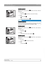
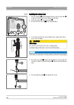
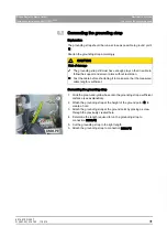
2. Drill the holes (6 mm (1/4") masonry drill bit) and insert the wall plugs.

3. Fasten the chassis firmly to the wall with three screws.

A

IMPORTANT

For concealed installation (A), the control cable is drawn into the chassis 

from the rear. For surface installation it is drawn in from underneath.

B

Summary of Contents for Heliodent plus

Page 1: ...NNKOMNM ebiflabkqmirp k W b f f HELIODENT PLUS 7mA DC 7mA DC 70kV 60kV S 008...

Page 2: ......

Page 3: ...pter 16 5 1 1 Preparation 16 5 1 2 Installation concealed installation 17 5 1 3 Installation surface installation 18 5 2 Installing the support arm and scissor arm 19 5 2 1 Preparation 19 5 2 2 Instal...

Page 4: ...llation option 6 44 6 4 9 Installation option 6 1 46 6 4 10 Installation option 7 49 6 4 11 Installation option 8 50 6 5 Completion 51 6 6 Preparing the power connection 51 7 Starting up 53 7 1 Functi...

Page 5: ...tructions HELIODENTPLUS Table of contents b 9 2 Service routines 68 9 2 1 Operation 68 9 2 2 Service routine S15 69 9 3 Replacing old units 70 9 3 1 Overview 70 9 3 2 Replacement of horizontally mount...

Page 6: ...mation provided in this document Such information is highlighted as follows Tip Information on making work easier DANGER An imminent danger that could result in serious bodily injury or death WARNING...

Page 7: ...number List Identifies a list Command menu item Identifies commands menu items or quotations DANGER Potentially lethal shock hazard It is essential that you switch the line voltage OFF at the main sw...

Page 8: ...ices see also Installation Requirements Chapter on EMC If this proves to be unavoidable the unit should be monitored to ensure that it is used properly CAUTION Electrical components of the unit can be...

Page 9: ...g Door contact safety circuit S7 empty Installation option 1 Installation option 1 Release in the treatment room without remote control Release Manual release S3 empty Installation option 2 Installati...

Page 10: ...tion option 6 Release outside of the X ray room with remote control door contact sa fety circuit Door contact Door contact S7 wired to the wall adapter Release Manual release S3 or Remote control rele...

Page 11: ...tallation option 7 Installation option 7 Release outside of the X ray room with Remote Timer door contact sa fety circuit Door contact Door contact S7 Release Release key on the control membrane S4 em...

Page 12: ...se perform an incoming inspection immediately after delivery 1 Check the delivery note to ensure that the consignment is complete 2 Check whether the product shows any visible signs of damage If retur...

Page 13: ...m a selected dealer The wall anchors and screws should be identical for every attachment point Alternatively an anchor plate can be used as a counter bearing In this case M8 threaded rods of the appro...

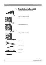
Page 14: ...2 Required tools and auxiliary materials Drill hammer drill general purpose Suitable drill and or suitable hammer drill Masonry drill bit 10 mm 3 8 Masonry drill bit 6 mm 1 4 Wood drill bit 6 mm 1 4 M...

Page 15: ...nsion size 13 mm Retaining ring pliers external Retaining ring pliers for outside rings shafts Drift punch Drift punch Ammeter Multimeter or ammeter battery operated Bender tester Test unit for device...

Page 16: ...ble bushings B and F in the drilling template 2 Pull the cable through the cable bushings B and F 3 Align the drilling template using a spirit level and attach it to the wall 4 Center punch the fasten...

Page 17: ...prepared installation location 4 Pull the power cable through the opening B in the wall adapter 5 For remote control Remote Timeronly cable L6 or L9 Pull the cable through the opening F in the wall a...

Page 18: ...ign the wall adapter with a spirit level and attach the wall adapter securely with suitable screws and washers depending on the type of attachment 5 Insert the power cable into the mounting plate from...

Page 19: ...rt the support arm into the bearing U 3 After insertion secure the support arm with a retaining ring W to prevent it from getting lifted out 4 Unlock the housing A by pressing the housing shells toget...

Page 20: ...Remove the scissor arm P3 from the packaging 4 For transport and for the next installation step support the scissor arm on your shoulder 5 Route the arm cable L1 downwards through the arm and insert t...

Page 21: ...issor arm b 7 Snap the retaining ring into the groove G 8 Push the arm cable L1 through the support arm 9 Disconnect the arm cable L1 and the grounding strap C in the accessible area 10 Thread the fer...

Page 22: ...g 12 Pull the arm cable L1 downward through the bearing 13 Check the support arm with the spirit level If necessary loosen the bearing mount 4 nuts and place the shim X underneath 5 3 Preparing the pr...

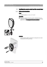
Page 23: ...1 Wall mounted installation empty Scope For installation options 2 3 4 5 6 6 1 7 and 8 empty Preparation Open remote Detach the housing of the remote control or the Remote Timer by carefully insertin...

Page 24: ...timer Installation Instructions HELIODENTPLUS 2 Drill the holes 6 mm 1 4 masonry drill bit and insert the wall plugs 3 Fasten the chassis firmly to the wall with three screws A IMPORTANT For conceale...

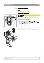
Page 25: ...empty Installation step 1 Remote Timer 1 Unscrew and remove the clamp A from board DX4 2 Remove cable L2 from connecting strip X103 on PC board DX4 Cable L2 is no longer required 3 Loosen the six scre...

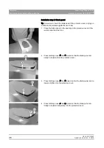
Page 26: ...on a table and is pressed against its own body 1 Place the blank panel on the opening in the protective cover of the wall module from the front 2 Press latching noses B and C inward so that the blank...

Page 27: ...he manual release holder 5 5 1 Installation on the wall empty Scope For installation options 1 2 3 4 5 6 6 1 and 8 empty Installation 1 Drill the hole for the holder at the desired position 2 Insert t...

Page 28: ...d adhesive tape at the holder 6 Adhere the holder to the front of the protective cover to match the drilled hole watch for top bottom alignment 7 Fasten the holder tight Use the supplied M4x16 screw w...

Page 29: ...cation 1 Remove the remote control release button S9 from the protective cover 2 Turn the protective cover over on its back You will see a hexagonal recess M 3 Drill a 4 3 mm 3 16 hole at the center o...

Page 30: ...6 Electrical connection 6 1 Connecting the arm cable Connect the arm cable to terminal strip X100 on the opposite side so that the lead color codes match Lead colors from top to bottom on terminal st...

Page 31: ...icient distance see explanation 2 Widen the grounding strap at the height of the ground point E to create a hole 3 Attach the grounding strap at the ground point by placing a screw through the previou...

Page 32: ...ing the control panel 6 3 1 Direct connection standard empty Scope For installation options 1 2 4 6 and 6 1 empty Connection 1 Plug cable L2 coming from PC board DX4onto connecting strip X400 of PC bo...

Page 33: ...nnection 1 Plug cable L6 into the connecting strip X400 of PC boardDX1 2 Secure cable L6 with the shielding clamp D 3 Connect cable L6 to strips X105 and X106 of PC board DX4 4 Secure cable L6 with th...

Page 34: ...S4 Directly connected to control board DX4 Remote control release key S9 Integrated in remote control housing Door contact safety circuit S7 6 4 2 Overview NOTICE Only one release button may be connec...

Page 35: ...tside of the X ray room with remote control See section Installation option 4 41 5 Release outside of the X ray room with Remote Timer See section Installation option 5 43 Installation with manual rel...

Page 36: ...act safety circuit Installation with release button on control membrane S4 See section Installation option 7 49 NOTICE Service routine S15 value Off 8 Release outside of the X ray room with Remote Tim...

Page 37: ...llation 1 Connect manual release S3 coiled cable to X401 on board DX1 at connectors X401 1 and X401 4 2 Secure the coiled cable with the shielding clamp B 3 Check the setting of switch S1 on PC board...

Page 38: ...le The holder for manual release S3 was attached to the cover of the remote control See section Installation on the protective cover of the remote control 29 empty Installation of cable L9 on DX1 1 Co...

Page 39: ...vice routine S15 69 empty Installation with manual release S3 Connect cable L9 and coiled cable L3 to the 3 pin terminal as shown Cable drawn in black concealed installation Cable drawn in gray surfac...

Page 40: ...utton on control membrane S4 1 Set switch S1 on PC board DX4 to internal see section Selection of the release button 68 2 Check the switch setting of S2 Switch S2 must be set to ON see section Service...

Page 41: ...r 23 Only with use of the manual release S3 coiled cable The holder for manual release S3 was attached to the cover of the remote control See section Installation on the protective cover of the remote...

Page 42: ...Check the setting of switch S2 on PC board DX4 Switch S2 must be set to ON see section Service routine S15 69 empty Installation with manual release S3 Connect cable L9 and coiled cable L3 to the 3 p...

Page 43: ...th release button on control membrane S4 1 Set switch S1 to internal see section on Selection of the release button 68 2 Check the switch setting of S2 Switch S2 must be set to ON see section Service...

Page 44: ...S3 coiled cable The holder for manual release S3 was attached to the cover of the remote control See section Installation on the protective cover of the remote control 29 empty Installation of cable L...

Page 45: ...heck the setting of switch S2 on PC board DX4 Switch S2 must be set to ON see section Service routine S15 69 empty Installation with manual release S3 Connect cable L9 and coiled cable L3 to the 3 pin...

Page 46: ...S3 or Remote control release key S9 As in installation version 6 empty Exception Door contact wired via remote control empty Prerequisites The remote control has been installed see section Installing...

Page 47: ...e 3 pin terminal as shown Cable drawn in black concealed installation Cable drawn in gray surface installation 1 Connect the shield of cable L9 to the shield of door contact D underneath the strain re...

Page 48: ...tact cable D to the 3 pin terminal as shown Cable drawn in black concealed installation Cable drawn in gray surface installation 1 Connect the shield of cable L9 to the shield of spiral cable L3 and t...

Page 49: ...een installed see section Installing the remote control remote timer 23 The Remote Timer has been modified see section Modifying the remote timer 25 empty Installation 1 Use the clamp W to fasten the...

Page 50: ...ying the remote timer 25 The holder for manual release S3 has been attached next to the Remote Timer empty Installation 1 Use the clamp W to fasten the manual release cable L3 and the door contact cab...

Page 51: ...a length of cable L1 to the left of the bearing block and secure the cable roll with a cable tie 6 6 Preparing the power connection empty General Power connection of DX1 empty X100 NOTICE The Helioden...

Page 52: ...able to X200 on DX1 Do not connect it due to initial test of protective ground wire and device leakage current see X200 1 L1 phase 1 X200 2 N Do not use X200 3 N X200 4 PE empty 2 phase connection Att...

Page 53: ...urrent test 56 Record the measured values in chapter 3 of the document Inspection maintenance and safety related check 2 Connect the power cable now empty Step 2 Check the function of the X ray tube a...

Page 54: ...ing installation off 2 Remove the power cable from connector X200 on PC board DX1 empty Visual check 1 Check the assembly and firm seating of the ground conductor 2 Check the main fuse F200 F201 3 Che...

Page 55: ...the test current for at least 5 seconds between protective wire connection X200 PE board DX1 and ground connection B X ray tube assembly 2 Read the voltage drop at the voltmeter and the current at th...

Page 56: ...ltmeter Alternative Complete test units e g the Bender tester fulfill these requirements as well empty Equivalent device leakage current measurement Test assembly 1 Connect the measurement voltage sou...

Page 57: ...mA 7 1 4 Checking the X ray tube assembly 1 Switch on the building installation or the emergency circuit to which the HELIODENTPLUS was connected 2 Switch the unit on 3 Monitor the self test 4 Select...

Page 58: ...1 Switch the unit off 2 Set the ammeter to the 10 mA DC measuring range 3 Connect the ammeter to the two outer X600 connectors on board DX1 4 Switch the unit on 5 Set the radiation time to 3 2 seconds...

Page 59: ...llation Instructions HELIODENTPLUS Functional test b empty Completion 1 Switch the unit off 2 Remove the measuring wires of the ammeter from connector X600 3 Reattach the housing on the wall module em...

Page 60: ...ation 1 Switch the X ray unit on 2 Wait until the self test is finished operational readiness signal must be lit The display reading shows the radiation time and a patient symbol 3 Set an exposure tim...

Page 61: ...Tolerance The permitted tolerance of the exposure time and high voltage is 10 empty In case of error Radiation time outside of tolerance limits Replace board DX4 High voltage outside of tolerance lim...

Page 62: ...LUS 7 2 Attaching the housing covers 7 2 1 Support arm cover 1 Set the cover of the arm connection onto the wall module as shown between the support arm and the wall 2 Attach the housing shells A and...

Page 63: ...ns HELIODENTPLUS Attaching the housing covers b 2 Attach the protective cover of the wall module locking it into place at the top first 3 Attach the cover with two screws from underneath 4 Only with m...

Page 64: ...tions HELIODENTPLUS 7 2 3 Remote control 1 Only with manual release S3 coiled cable Place the ferrite core of the coiled cable inside the housing 2 Mount the cover of the remote control on top of the...

Page 65: ...pening in the wall To do this fasten the coiled cable with the strain relief clamp S 2 Mount the cover of the Remote Timer on top of the chassis from above 3 Snap the cover into the chassis at the bot...

Page 66: ...dition the user can activate preselected service routines via his own service area see operating instructions Service routine Function S05 Selection of sensor type S04 Selection of film type S06 Selec...

Page 67: ...Passport with the customer 6 Separate the carbon copy of the Installation Report Warranty Passport 7 Hand over the original of the Installation Report Warranty Passport CUSTOMER S COPY to the customer...

Page 68: ...3 or a release button with remote control S9 When delivered slide switch S1 is set to external 9 2 Service routines 9 2 1 Operation 1 Switch the unit on 2 Press the Film key the Sensor key and the Bit...

Page 69: ...can be bypassed via hardware on DX4 slide switch S2 See section Setting switch S1 and S2 on DX4 68 Slide switch S2 On safety circuit bypassed Slide switch S2 Off safety circuit activated If the settin...

Page 70: ...S See the section on Replacement of horizontally mounted old units with an adapter plate 71 The HELIODENTPLUS has a lower knock out elongated hole for the replacement of vertically mounted old units S...

Page 71: ...tes A check was performed to ensure that the mounting dimensions of the old unit match those of the adapter plate empty CAUTION The on site electrical installation must be performed according to the v...

Page 72: ...ficiently if necessary 2 Only if a remote timer is used Pull cable L6 into the wall 3 Only if a remote control is used Pull cable L9 into the wall 4 Pick up the adapter plate 5 Insert the power cable...

Page 73: ...ongated hole installation version If the distance between the drill holes is less than 281 mm 11 the lower knock out elongated hole G of the wall adapter must be used empty Suitable old units Progeny...

Page 74: ...eck whether a conduit with a int of at least 12mm 1 2 is available for cable L6 or L9 6 Elongated hole installation version only Unscrew the cables from board DX1 on terminal strips X500 and X501 7 El...

Page 75: ...lation steps Perform the remaining installation steps as described in the Chapter on Installation 16 Adaptation of the remaining installation steps due to replacement of an old unit Elongated hole ins...

Page 76: ...t K p a p d e OMNM p W m d a PRMTKMPNKMNKMTKMO NNKOMNM KJk KW NNP QQO p a p d e rp W c PN SQSOR _ d K K p a p ii QUPR p a I p NMM I k OUOTP rp l k SO NQ VTO a PRMT...

Reviews: