


②
At this moment, last 2 digits of the nixie tube display “01” which means the first group setting begins.
Press “
” to the next step.
③
By this time, mode icon will flicker and press
“
”
to choose timing on mode. Press “
” to confirm
your choice and go to the next step.
④
By this time, the last 2 digits of the nixie tube will flicker and press “
” or “
” to adjust temperature
and set the temperature of the inlet water. Press “
” to confirm and move to the next step.
⑤
By this time, the first 2 digits of the nixie tube will flicker and press “
” or “
” to adjust time of timing
on. Press “
” to confirm and switch to minute setting automatically. The last 2 digits of the nixie
tube will flicker and press “
” or “
” to adjust minute setting of timing on.(minimal unit of minute
adjustment: 15 minutes) .
⑥
Press
“
”
to confirm. The first group setting is finished and “
” will be constantly light.
When processing the second timing setting, repeat the 1-2 operation above. When the nixie tube displays
“01” and flicker, press“
” or “
” to choose the timing on group. When the nixie tube displays “ 02 ”
which means setting timing on function of the second group.
Refers the timing on setting operation of group 1 to set that of group 2.
●
Long press
“
”
for 3s to return to the previous interface to reset the parameter during setting clock
timing.
b. Timing off setting
①
Long press
“
”
for 3s in the main interface to enter function interface. Press “
” circularly to
enter timing off function. “
” will flicker and press “
” to enter timing off setting.
②
At this moment, the last 2 digits of the nixie tube display “01” which means the first group setting begins.
Press “
” to the next step.
③
By this time, the first 2 digits of the nixie tube will flicker and press “
” or “
” to adjust time of
timing off. Press “
” to confirm and switch to minute setting automatically. The last 2 digits of the
nixie tube will flicker and press “
” or “
” to adjust minute setting of timing off. Press “
” to
confirm. The first group setting is finished and “
” will be constantly light.
④
When processing timing setting of group 2, repeat the 1-2 operation above. When the nixie tube
displays “01” and flicker, press “
” or “
” to choose the timing off group. When the nixie tube
displays “02”which means setting timing off function of the second group.
Refers the timing off setting operation of group 1 to set that of group 2.
c. Cancel all timing on/off settings
Long press “
” for 3s to enter function interface. “
” clock icon will flicker and press “
”
to choose the timing function. “
” and “
” flicker simultaneously means choosing to cancel all
timing functions.
Press “
” to cancel timing settings. “
” and “
” both will be extinguished.
16.1.2 Functions of combination key
Force cooling function
Press
“
”
and
“
”
simultaneously for 3s in the main interface to enter into force cooling mode.
The force cooling mode icon will be constantly light.
Press “
” button and “
” button simultaneously for 3s to quit force cooling mode. The unit will
enter power off mode automatically when quitting force cooling mode.
16.1.3 Auto-lock(unlock) function
If don’t operate the controller in 60s, the keyboard will lock automatically. Press “
”and “
”
50
Summary of Contents for SCV-100EA
Page 1: ...SCV xxEA SERVICE MANUAL AIR COOLED MINI CHILLER UNIT AIR CONDITIONING...
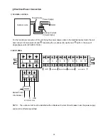
Page 16: ...7 Wiring Diagram SCV 50EA SCV 70EA 14...
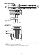
Page 17: ...SCV 100EA 15...
Page 18: ...SCV 120EA SCV 140EA SCV 160EA 16...
Page 28: ...11 Water Pressure Drop SCV 50EA SCV 70EA SCV 100EA Heat exchanger pressure drop water side 26...
Page 29: ...SCV 120EA SCV 140EA 27...
Page 30: ...SCV 160EA 28...
Page 88: ...18 Optional Accessories No Name Specification Remark 1 Wired controller KJR 120F Customized 86...
Page 91: ...Exploded view of unit SCV 50EA 22 7 22 6 22 5 22 4 22 2 22 1 22 3 89...
Page 94: ...Exploded view of unit SCV 70EA 22 7 22 6 22 5 22 4 22 2 22 1 22 3 92...
Page 97: ...Exploded view of unit SCV 100EA 25 1 25 2 25 3 25 6 25 7 25 4 25 5 25 9 25 8 95...
Page 100: ...Exploded view of unit SCV 120EA 25 1 25 2 25 3 25 4 25 5 25 6 25 7 25 9 25 8 25 10 25 11 98...
Page 103: ...Exploded view of unit SCV 140EA 25 1 25 2 25 3 25 4 25 5 25 6 25 7 25 9 25 8 25 10 25 11 101...
Page 106: ...Exploded view of unit SCV 160EA 25 1 25 2 25 3 25 4 25 5 25 6 25 7 25 9 25 8 25 10 25 11 104...


