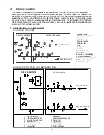


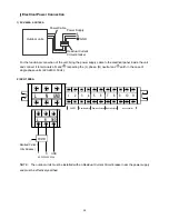


3) SCV-120EA, SCV-140EA, SCV-160EA
N
C
3
1
2
6
4
5
7
8
GND
9
10
11
B
A
PUMP2
Remote alarm
Remote shutdown Remote cooling/heating
wire controller
AC 380-415V 50Hz
Residual Current
Circuit-breaker
GND
N
C
GND
B
A
A
B
C
N
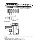
Auxiliary Connection
1) SCV-50EA, SCV-70EA
AC CAN TACTOR
L
N
220~240 V
220~240 V
L
N
Addtitiona l pum p
Reserved
1
2
1
2
L
1
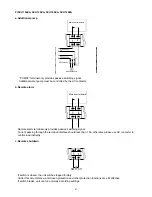
PUMP2
BOIL
ON/OFF
Switch
1.“PUMP2”wiring terminal supplies ON/OFF signals only. Standby water pump must be controlled by the AC
contactor.
2.“ON/OFF” wiring terminal L supplies 220V voltage.
The unit must be powered off when connecting the remote control switch.
When the remote control switch is closed, the unit is forced to shut down.
40
Summary of Contents for SCV-100EA
Page 1: ...SCV xxEA SERVICE MANUAL AIR COOLED MINI CHILLER UNIT AIR CONDITIONING...
Page 16: ...7 Wiring Diagram SCV 50EA SCV 70EA 14...
Page 17: ...SCV 100EA 15...
Page 18: ...SCV 120EA SCV 140EA SCV 160EA 16...
Page 28: ...11 Water Pressure Drop SCV 50EA SCV 70EA SCV 100EA Heat exchanger pressure drop water side 26...
Page 29: ...SCV 120EA SCV 140EA 27...
Page 30: ...SCV 160EA 28...
Page 88: ...18 Optional Accessories No Name Specification Remark 1 Wired controller KJR 120F Customized 86...
Page 91: ...Exploded view of unit SCV 50EA 22 7 22 6 22 5 22 4 22 2 22 1 22 3 89...
Page 94: ...Exploded view of unit SCV 70EA 22 7 22 6 22 5 22 4 22 2 22 1 22 3 92...
Page 97: ...Exploded view of unit SCV 100EA 25 1 25 2 25 3 25 6 25 7 25 4 25 5 25 9 25 8 95...
Page 100: ...Exploded view of unit SCV 120EA 25 1 25 2 25 3 25 4 25 5 25 6 25 7 25 9 25 8 25 10 25 11 98...
Page 103: ...Exploded view of unit SCV 140EA 25 1 25 2 25 3 25 4 25 5 25 6 25 7 25 9 25 8 25 10 25 11 101...
Page 106: ...Exploded view of unit SCV 160EA 25 1 25 2 25 3 25 4 25 5 25 6 25 7 25 9 25 8 25 10 25 11 104...