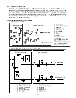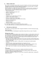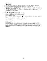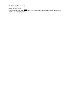
j) Electrical Power Connection
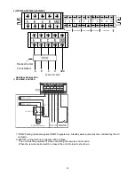
1) SCV-50EA, SCV-70EA
Outdoor units
Power Cable
Power Supply
Residual Current
CIrcuit-breaker
L
N
GND
For the functional connection of the unit, bring the power supply cable to the electrical panel inside the unit
and connect it to terminals L-N and
respecting the (L) phase, (N) neutral and
earth in the case of
single phase units (220-240V~50Hz).
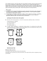
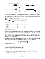
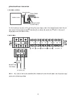
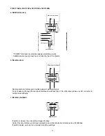
2) SCV-100EA
N
L
3
1
2
6
4
5
7
8
GND
PUMP2
Remote alarm Remote shutdownRemote cooling/heating
wire controller
9
10 11
N
L
GND
AC 220-240V 50Hz
L
N
Residual Current
Circuit-breaker
GND
NOTE: The outdoor units must be installed with an Residual Current Circuit-breaker near the power supply
and must be effectively earthed.
39
Summary of Contents for SCV-100EA
Page 1: ...SCV xxEA SERVICE MANUAL AIR COOLED MINI CHILLER UNIT AIR CONDITIONING...
Page 16: ...7 Wiring Diagram SCV 50EA SCV 70EA 14...
Page 17: ...SCV 100EA 15...
Page 18: ...SCV 120EA SCV 140EA SCV 160EA 16...
Page 28: ...11 Water Pressure Drop SCV 50EA SCV 70EA SCV 100EA Heat exchanger pressure drop water side 26...
Page 29: ...SCV 120EA SCV 140EA 27...
Page 30: ...SCV 160EA 28...
Page 88: ...18 Optional Accessories No Name Specification Remark 1 Wired controller KJR 120F Customized 86...
Page 91: ...Exploded view of unit SCV 50EA 22 7 22 6 22 5 22 4 22 2 22 1 22 3 89...
Page 94: ...Exploded view of unit SCV 70EA 22 7 22 6 22 5 22 4 22 2 22 1 22 3 92...
Page 97: ...Exploded view of unit SCV 100EA 25 1 25 2 25 3 25 6 25 7 25 4 25 5 25 9 25 8 95...
Page 100: ...Exploded view of unit SCV 120EA 25 1 25 2 25 3 25 4 25 5 25 6 25 7 25 9 25 8 25 10 25 11 98...
Page 103: ...Exploded view of unit SCV 140EA 25 1 25 2 25 3 25 4 25 5 25 6 25 7 25 9 25 8 25 10 25 11 101...
Page 106: ...Exploded view of unit SCV 160EA 25 1 25 2 25 3 25 4 25 5 25 6 25 7 25 9 25 8 25 10 25 11 104...


