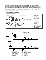


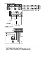


If the installation requires a useful head higher than that obtained by installing a pump assembly and storage
tank, it is recommended that an additional pump is installed on the unit. Provided the additional pump
installed inside of unit, the pump must connected close to plate heat exchanger. Provided the pump installed
outside of unit, the pump shall be connected at water pipe’s outlet. The pump can be easily installed on the
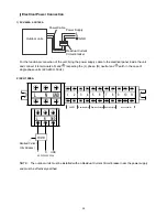
unit by removing the pump connection pipe. Connect to terminal PL,PN on the electric panel.
Important
1) The chillers must be provided with a filling/top-up system connected to the return line and a drain cock in
the lowest part of the installation. Installations containing anti-freeze or covered by specific legislation
must be fitted with hydraulic disconnections.
2) The manufacturer is not liable for obstruction, breakage or noise resulting from the failure to install filters
or vibration dampers. Particular types of water used for filling or topping up must be treated with
appropriate treatment systems. For reference values, see the table.
e).Design of the store tank in the system
kW is the unit for cooling capacity, L is the unit for (G) minimum water flow volume in the formula.
Comfortable type air conditioner
G= cooling capacity×2.6L
Process type cooling
G= cooling capacity×7.4L
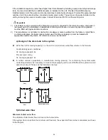
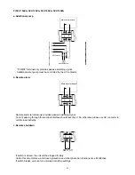
In certain occasion (especially in manufacture cooling process), for conforming the system water
content requirement, it’s necessary to mount a tank equipping with a cut-off baffle at the system to avoid
water short-circuit, Please see the following schemes:
Error
Recommendation
Error
Recommendation
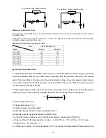
f).Chilled water flow
Minimum chilled water flow
The minimum chilled water flow is shown in the below table.
If the system flow is less than the minimum unit flow rate, the evaporator flow can be recalculated, as shown
in the diagram.
34
Summary of Contents for SCV-100EA
Page 1: ...SCV xxEA SERVICE MANUAL AIR COOLED MINI CHILLER UNIT AIR CONDITIONING...
Page 16: ...7 Wiring Diagram SCV 50EA SCV 70EA 14...
Page 17: ...SCV 100EA 15...
Page 18: ...SCV 120EA SCV 140EA SCV 160EA 16...
Page 28: ...11 Water Pressure Drop SCV 50EA SCV 70EA SCV 100EA Heat exchanger pressure drop water side 26...
Page 29: ...SCV 120EA SCV 140EA 27...
Page 30: ...SCV 160EA 28...
Page 88: ...18 Optional Accessories No Name Specification Remark 1 Wired controller KJR 120F Customized 86...
Page 91: ...Exploded view of unit SCV 50EA 22 7 22 6 22 5 22 4 22 2 22 1 22 3 89...
Page 94: ...Exploded view of unit SCV 70EA 22 7 22 6 22 5 22 4 22 2 22 1 22 3 92...
Page 97: ...Exploded view of unit SCV 100EA 25 1 25 2 25 3 25 6 25 7 25 4 25 5 25 9 25 8 95...
Page 100: ...Exploded view of unit SCV 120EA 25 1 25 2 25 3 25 4 25 5 25 6 25 7 25 9 25 8 25 10 25 11 98...
Page 103: ...Exploded view of unit SCV 140EA 25 1 25 2 25 3 25 4 25 5 25 6 25 7 25 9 25 8 25 10 25 11 101...
Page 106: ...Exploded view of unit SCV 160EA 25 1 25 2 25 3 25 4 25 5 25 6 25 7 25 9 25 8 25 10 25 11 104...