| 127
Maps |
Argus Radar Operator Manual
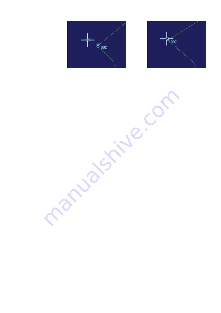
Moving the Trackball with the point hooked
Releasing the point
Clicking on it again, the object will be hooked to the trackball cursor again (the lines will not
move while the pointer moves, but the highlighting symbol will). Once moved to where
desired, press the left SK again to release it in the new place.
Selection and movement by means of the editable labels and buttons
The position of selected objects and also the selection of an object can be changed placing
the trackball pointer over the coordinat
e labels of the figure to be changed. For example, if
we wish to change the latitude minutes of the “LIVORNO” text, place the trackball pointer on
the label indicating the latitude minutes of the selected text (44.063’). The Help Line will show
“Decrease”, Enter Value” and “Increase”. Pressing the left and right SKs, the value in the label will
be decreased or increased one step (0.001’) for each press. Holding them pressed, after a few
seconds, the value will change quickly in steps of 0.010’. Otherwise, by pressing the centre SK,
the numeric keypad will be displayed giving the possibility to insert figures directly.
Changing the degrees instead of the minutes, or changing the minutes too much, the object
could disappear from the maximum range scale of the PPI. The “N” and “E” buttons’ functions
are to specify the latitude and longitude orientations (North or South, East or West).
All the changed values will be applied to the selected item. In the example above, the
“LIVORNO” text was already selected. To select another object the trackball pointer must be
placed on the corresponding label. As in the example it must be placed on “Point 3” to select
a point, “Text 0” to select a text and “Sym 0” to select a symbol. The help line will appear the
same as when changing the latitude figure, so pressing the right SK the object following the
one already selected will now be selected and so on. For example, pressing the right SK, with
the trackball pointer on “Point 3”, the point 4 should be selected, but the label could be show-
ing “Point 3 E“, “E” stands for end, normally the selection on the screen indicates the start point
of a segment. The “Point 3 E” case means that the segment starting from the point 3 ends the
multi-line and the selection “Point 3 E” allows anchoring the final point of the multi-line, which
is not the point 4, but the ending point of the segment 3.
To insert new texts or new symbols “Ins Text” or “Ins Sym” must be pressed, and the new object
will be placed in the centre of the map (normally own ship position). Once the new object is
placed, follow the above procedure to move it where needed.
To insert new lines the operator must insert new points. To do that the “Ins Point” labelled
button must be pressed. A list will be visualised under the button, with the 4 possibilities of
insertion modes:
1.
Insert New Point After Selected. The point will be inserted after the selected one, re-num-
bering the points following the selected one. If the selected point was connected to another
one, the new point will be connected to it. The new inserted point will be temporarily placed
in the same position of the end of the selected and the beginning of the following, and then
the operator can move it as desired.
2.
Insert New Point Before Selected. The point will be temporarily inserted in the place of the
selected one. It will be in the same position of the selected and of the previous one, and
then the operator can move it as desired. The point selected and the following ones will be
re-numbered.
3.
Insert New Point Starting New Segment. The new point will be placed in the centre of the
map, creating two points which are intended to be the start and the end of a new segment.
The operator can move them as desired.
Summary of Contents for ARGUS FMCW 3G
Page 1: ...ENGLISH ARGUSRADAR SYSTEM User Manual navico commercial com...
Page 2: ......
Page 149: ......
Page 150: ...988 10185 004...


