background image

SVD 800 HD

9

ENGLISHENGLISHENGLISHENGLISHENGLISH

3.1 Batteries

Handling the remote control and batteries:

- Avoid exposing the remote control to heat and humidity.

- When not using the remote control for a long period of

time, remove the batteries.

- Do not use new and old batteries together or batteries

of  a different voltage or type.

- Do not drop or mishandle the remote control.

- Use the remote control within its operating range (about

10 metres and a 30

°

 angle)

Note: 

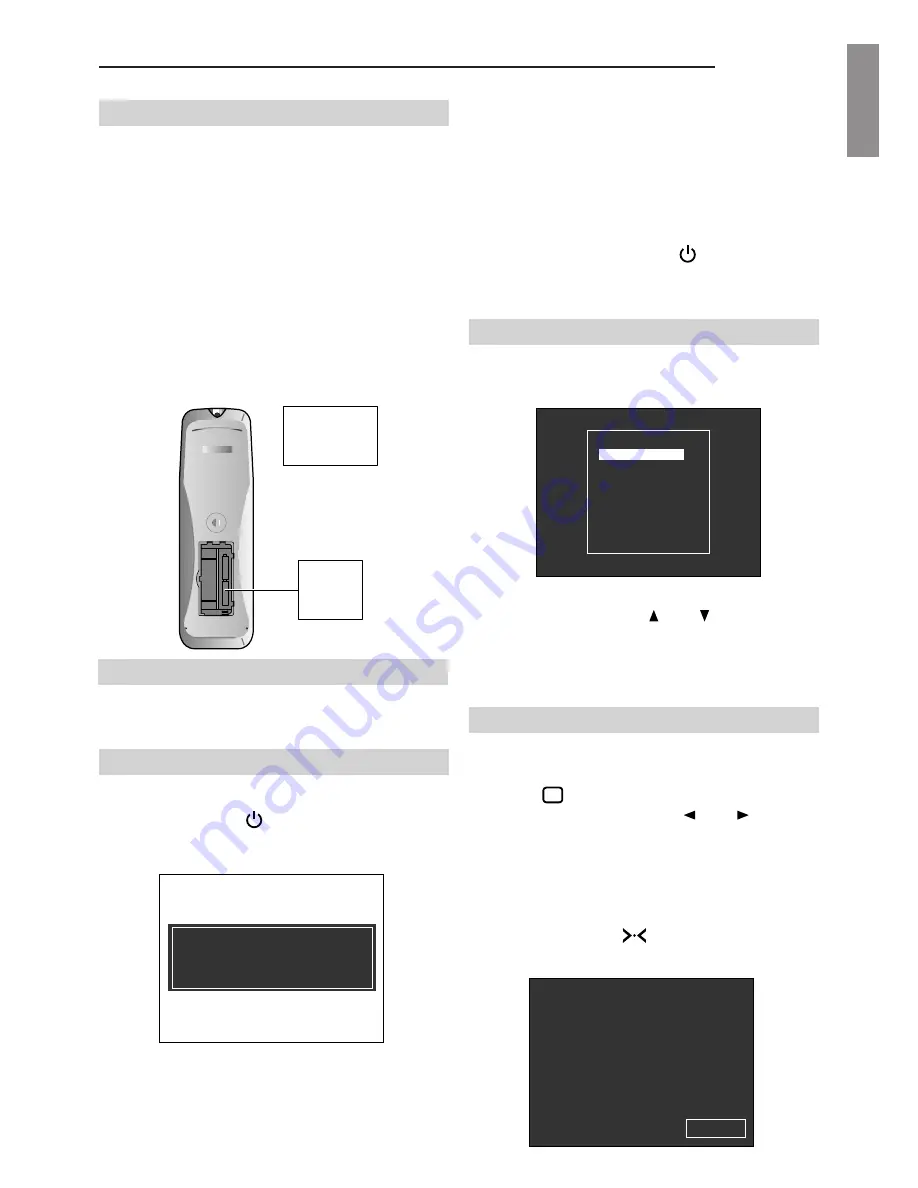
The RC3100 remote control is powered by two AA
batteries.

3.2 RC 3100 User Remote Control

Read this chapter through carefully before altering any
values or making any adjustments.

3.3 Projector Power On

- Press the mains switch. A red LED turns on on the Stand-

by back panel, press 

 or one of the buttons 1

÷

9.

- The red LED becomes green ON.
- A white screen will appear with the following message:

2 AA

1.5 V

batteries

RC 3100 

BACK OF THE

REMOTE CONTROL

Fig. 5

- Press any button to eliminate the initial screen and to see

the image immediately after having switched the projector
on in the case, for instance, it has already been adjusted
and warming up is unnecessary.

- Warm-up time can be modified and/or excluded, 

see par.

3.21 OSD OPTIONS page 14.

- To switch the projector off press 

  and then move the

power switch to OFF.

3.4 Input selection

To select the input directly use a numerical button or:
Press 

AV

/O. The input menu will appear;

FOR AN OPTIMAL USE THE WHITE

PATTERN WILL REMAIN ON THE 

SCREEN FOR 10 MINUTES !

FOR IMMEDIATE USE PRESS ESC

Fig. 6

Select the right input withthe    up or   down arrows and
press ENTER. The selected input selected will appear with
a message on the screen.
Note: 

With the Y Cr Cb 15KHz signals use input 5


 With the R G B 15KHz signals use input 7

3.5 Picture adjustment

To change the value of CONTRAST, BRIGHTNESS,
COLOUR, HVE (NTSC STANDARD) AND PEAKING
,

press the 

 button sequentially. One of the five

adjustments will appear. Press the   left or   right arrow
to modify the value, press MEMO to store the new value.

N.B.

MEMO should be pressed when one of the
adjustment functions is displayed.

The stored values are specific for the bank in use and
can be recalled with the 

 button.

Fig. 7

-    INPUTS    -

1      -      VIDEO1

2      -      VIDEO2
3      -      S-VHS1
4      -      S-VHS2
5      -      YCRCB 15K
6      -      YCRCB
7      -      RGB 15K
8      -      RGB
9      -      VGA

- Always let the projector warm up for ten minutes after

switching it on.

- The message will disappear temporarily after about 10

seconds and will then return for 5 seconds. This will be
repeated at 40 second intervals.

CON      80

Fig. 8

Summary of Contents for SVD 800 HD

Page 1: ...VIDEO PROJECTOR USER AND INSTALLATION MANUAL MANUALE D USO E INSTALLAZIONE GEBRAUCHS UND INSTALLATIONSANLEITUNG MANUAL DE USO E INSTALACI N PROJECTOR SVD 800 HD...

Page 2: ...button 10 3 10 Normalised button 10 3 11 UPC button 10 3 12 Freeze button 10 3 13 Video Menu 11 3 14 UPC converter 11 3 15 Input Settings 12 3 16 Blanking 12 3 17 EHT NOISE RED 12 3 18 WHITE MENU 13...

Page 3: ...orizontal and vertical frequencies 30 5 8 5 How to store a new input signal 30 5 8 6 LOAD 30 5 8 7 COPY 31 5 8 8 MOVE 31 5 8 9 DELETE DEL 32 5 9 Installation types 32 5 10 Fine picture adjustments 32...

Page 4: ...rference will not occur in a particular installation If this equipment does cause harmful interference to radio or television reception which can be determined by turning the equipment off and on the...

Page 5: ...liminary adjustments must be performed by qualified service technicians 2 1 Projector identification The model and serial number are located on the projector s rear label Fig 1 Record the serial numbe...

Page 6: ...INPUT VEDE 2 3 Servicing Servicing must be carried out by qualified technicians Do not attempt to service the projector without the proper technical knowledge Opening the projector can expose personne...

Page 7: ...age in a different format for a long time The smaller picture could remain impressed on the screen for instance visualising a 16 9 image on a 4 3 screen or vice versa In this case we suggest reducing...

Page 8: ...This output can activate a relay with a current less than 10mA for example to enable a circuit for the automatic unwinding and rewinding of the motorised screen 16 Screen command It has 12V in output...

Page 9: ...To exit any menu To change the contrast brightness peaking hue and colour saturation values To access the aux menu To recall NORMALISED values of brightness contrast peaking hue and saturation To sel...

Page 10: ...can be modified and or excluded see par 3 21 OSD OPTIONS page 14 To switch the projector off press and then move the power switch to OFF 3 4 Input selection To select the input directly use a numeric...

Page 11: ...s recommended for video signal broadcasting Fig 9 3 8 Information INFO The INFO menu displays information on a current input signal Fig 10 16 9 Press INFO again The second part of the information will...

Page 12: ...UPC converter uses IQTV technology offering great video image improvements such as stability noise reduction less space between lines and increased contrast NOTE To switch the converter on or off pres...

Page 13: ...G EHT NOISE RED WHITE MENU Fig 21 INPUT SETTINGS CLAMP POS TLV SYNC AUTO OFF Press or Select CLAMP POS MANUAL INPUT SETTINGS CLAMP POS TLV SYNC MANUAL 20 OFF Fig 22 INPUT SETTINGS CLAMP POS TLV SYNC M...

Page 14: ...ENU QSD MANAGER UPC MANAGER INPUT SETTINGS BLANKING EHT NOISE RED WHITE MENU Fig 28 WHITE MENU SET TO 3200 K SET TO 6500 K SET TO 9300 K SET TO USER SET TO BANK EDIT PRESET 3 19 OPTIONS Press The MAIN...

Page 15: ...E TIME item sets the time the messages are displayed on the screen going from 2 to 9 seconds The MENU TIME item sets the time the menus are displayed on the screen going from 2 to 59 seconds The OSD O...

Page 16: ...the SERVICE MODE will you be able to alter deflection dimensions colour temperature select the installation type etc Press The MAIN MENU appears Press or Select INSTALL MENU MISCELLANEOUS TIMER FUNCT...

Page 17: ...jector on the floor or on the ceiling and center the screen see par 4 6 Projector centering page 23 maintaining the factory deflection settings 6 Carry out a precise focus adjustment acting on the len...

Page 18: ...or careless ceiling installation which must be effected by a qualified technician 4 3 2 Desk top front projection Attention The bottom of the projector must be parallel with the floor It is very impo...

Page 19: ...the value of A is 1 471x213 3 313 7 cm Note For 16 9 screen formats measure the width and refer to the nearest width value in the table 4 3 4 Ceiling front projection Use the ceiling assembly kit giv...

Page 20: ...their washers insert the left bracket and fix it using the same screws and washers as illustrated in the following figure Repeat for the right bracket Fig 46 SCREEN F R O N T 440 93 OBSERVE PARALLELI...

Page 21: ...roper adjustment 45 0 90 9 0 4 5 14 Fig 50 Attention Correct use of the spacers as shown in the tables is of paramount importance for perfect focus uniformity 4 5 1 Spacers changing To change the spac...

Page 22: ...5 2 0 0 3 0 0 2 1 0 2 0 3 0 3 0 18 1 1 2 0 3 0 0 3 2 2 0 0 2 0 3 1 1 0 3 0 80 GREEN BLUE RED 12 1 0 2 1 0 5 0 0 3 1 0 2 1 0 2 0 0 1 0 5 1 0 2 0 3 0 14 1 0 3 1 0 3 1 0 3 1 0 5 0 2 0 0 3 0 0 1 0 5 0 2...

Page 23: ...2 0 3 0 0 0 3 0 2 18 0 2 0 3 0 0 1 0 5 0 3 1 0 5 0 3 0 5 0 2 0 5 0 2 0 3 0 2 250 GREEN BLUE RED 12 0 3 0 3 0 3 0 3 0 0 0 0 0 3 0 3 0 0 14 0 3 0 2 0 3 0 2 0 3 0 2 0 3 0 2 0 5 0 5 0 0 0 0 0 0 18 0 0 0...

Page 24: ...e functions remote control RC3000 and selecting the most appropriate test signal SCREEN AND PROJECTOR CENTRE SCREEN CORDS OF THE SAME LENGTH Reference corner Reference corner Fig 53 4 8 Lens focus adj...

Page 25: ...IRE BLUE WIRE YELLOW WIRE DESK TOP FRONT PROJECTION RED Horizontal Deflection Connectors Vertical Deflection Connectors GREEN BLUE R G B RED WIRE BROWN WIRE BLUE WIRE YELLOW WIRE CEILING FRONT PROJECT...

Page 26: ...r the NTSC standard Resets the adjustments made Not active Not active Lights up the remote control buttons In the installation mode it lets you enter the convergence menu In the installation mode it l...

Page 27: ...5 3 How the RC 3000 remote control works The following paragraphs describe the functions of the RC3000 remote control Always leave the projector to warm up for ten minutes after switching it on The m...

Page 28: ...H H H H H H H H H H H H H H H H H H H H H H H H H H H H H H H H H H H H H H H H H H H H H H H H H H H H H H H H H H H H H H H H H H H H H H H H H H H H H H H H H H H H H H H H H H H H H H H H H H H H...

Page 29: ...e BLACK of the colour to adjust Press or to adjust Press Rsel Gsel Bsel Select the WHITE of the colour to adjust Press or to adjust Press MEMO when adjusting is finished N B When adjusting is finished...

Page 30: ...r in green Press or to scroll the letters of the alphabet and use the left or right arrows to move to the next letter Fig 78 MEMORY MANAGER EDIT BANK NAME LOAD COPY N 00 01 02 03 04 05 06 07 08 09 15...

Page 31: ...ENTER and the following will appear Fig 83 Press ENTER The menu will appear with the number of the bank where it is stored Press ESC to exit 5 8 6 LOAD This item on the MEMORY MANAGER menu allows the...

Page 32: ...08 09 15 6 15 7 31 5 31 5 31 2 48 4 64 3 71 7 50 60 70 60 60 00 60 76 N N N N N N N N PAL NTSC358 DOS VGA VGA 640 31K 10HZ VESA 1024 64K 60HZ UN 76HZ HOR VER F LABEL 01 BANK SIGNAL NAME PAL MOVE DEL...

Page 33: ...Press or Select the installation type Press ENTER to confirm Fig 103 OPTIONS MEMORY MANAGER INSTALL TYPE MISCELLANEOUS INSTALL TYPE DESKTOP FRONT DESKTOP REAR CEILING FRONT CEILING REAR Fig 104 Press...

Page 34: ...ft up or down Press or or to adjust 5 11 3 LINEARITY This function is used to modify the distance between the cross hatch lines until they are equal This adjustment is common to the three colours R G...

Page 35: ...XX ZONE SHIFT FINE 5 11 6 BOW Press or or to adjust 5 11 7 KEYSTONE Press or or to adjust 5 11 8 PINCUSHION Press or or to adjust 5 11 9 ZONES This function adjusts the red zones after having adjuste...

Page 36: ...If you press the RESET button when you are in the convergence setups CONV you will reset the convergence parameters and those of the zones of the three colours R G B If you press the RESET button when...

Page 37: ...is factory set at 6500 K 6 8 Automatic cut off The projector automatically carries out controls for better colour temperature stability at set intervals 6 9 Adjustments All projector adjustments excep...

Page 38: ...Zone adjustments installation mode Projector status info Video input selection Resettable adjustments installation mode Back lighting by pressing a dedicated button If no button is pressed the light...

Page 39: ...0 7 Vpp 75 Ohm termination TTL LEVEL sync input level positive or negative 75 Mhz 3dB video bandwidth 7 11 PC control Through the RS422 interface the projector can be controlled by a PC with specific...

Page 40: ...sed 6 GND 7 GND 8 GND 9 Not used 10 GND 11 Not used 12 Not used 13 H HV 14 V 15 Not used No pin Signal 1 GND 2 Not used 3 Not used 4 TX 5 Do not use 6 RX 7 Not used 8 Do not use 9 Do not use Luminance...

Page 41: ...push button has not been pressed The power cable is disconnected The projector is switched off The input setting is wrong The picture setup is wrong One or more fans have stopped A communication erro...

Page 42: ...delles galement fournis dans l emballage Pour cela UTILISER les trous ext rieurs de la patte et serrer avec un couple maximal de 25 Nm ATTENTION L installateur devra v rifier si le mur peut supporter...

Page 43: ...usement et enti rement cette notice Elle vous fournira les informations de base pour l utilisation du projecteur Installation r glages et proc dures pr liminaires qui requi rent l ouverture du project...

Page 44: ......

Reviews: