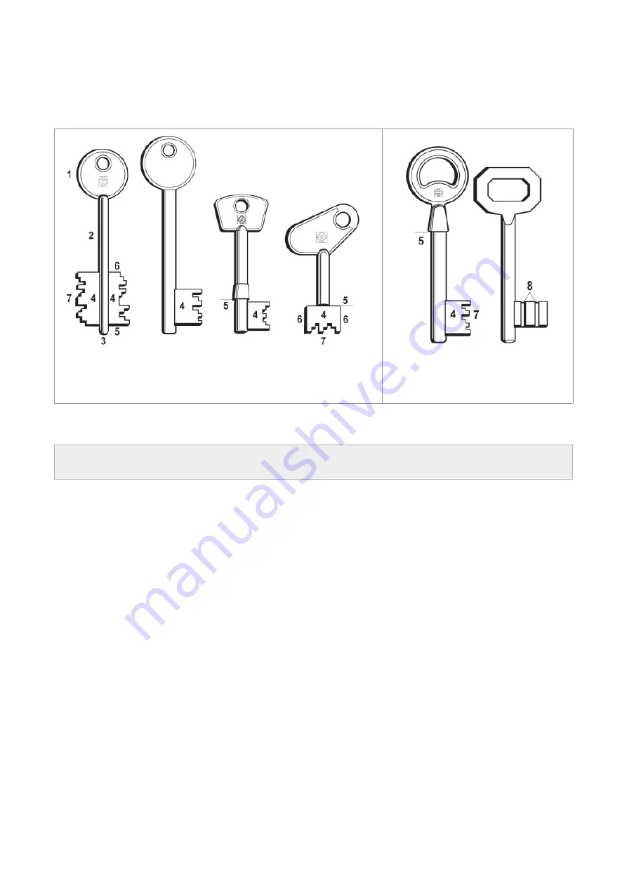
background image

TERMINOLOGY

For those inexperienced in the subject of keys and key cutting, below is an illustration of the most frequently used 
terms:

Keys with rear stops

and keys with vertical cuts:

STANDARD with

OMNIA MAX and OMNIA W MAX

Fig.2

1) Head

2) Stem

3) Tip

4) Bit

5) Stop

6) Side

7) Cuts

8) Vertical 

cuts


Operating Manual

OMNIA / OMNIA 650rpm / OMNIA MAX / OMNIA W MAX

Copyright Silca 2014

2

Summary of Contents for Omnia

Page 1: ...Operating Manual Original Instructions D442661XA vers 3 0 EN Omnia Omnia Max Omnia W Max Omnia 650rpm ...

Page 2: ...ty This document or any of its parts cannot be copied altered or reproduced without written authorization from the Manufacturer Keep the manual and look after it for the entire life cycle of the machine The information has been drawn up by the manufacturer in his own language Italian to provide users with the necessary indications to use the key cutting machine independently economically and safel...

Page 3: ...MAX clamp carriage for vertical cuts 20 5 5 7 OMNIA MAX OMNIA W MAX solution with a SINGLE CARRIAGE 21 5 6 Removing the clamp carriage 22 6 MACHINE INSTALLATION AND PREPARATION 23 6 1 Checking for damage 23 6 2 Environmental conditions 23 6 3 Positioning 23 6 4 Description of work station 23 6 5 Connection to the mains 23 7 MACHINE REGULATION AND UTILIZATION 24 7 1 Micrometric tracer point 24 7 2 ...

Page 4: ...artment 40 9 7 Replacing the ON OFF switch 40 9 8 Replacing the motor start button 41 9 9 Replacing the reset switch 41 9 10 Replacing the microswitch 42 9 11 Replacing the brush button 43 9 12 Replacing the plug socket filter 44 9 13 Replacing the relay 44 9 14 Replacing the lamp power box 45 9 15 Replacing the motor condenser 45 9 16 Replacing the Plexiglas shield 46 9 17 Replacing the lamp 47 9...

Page 5: ...ion of their physical sensorial or mental capacities Manufacturer s ID OMNIA has an ID plate located on the back of the machine showing the serial number Fig 1 see chap 10 DISPOSAL How to apply for after sales service Silca provides purchasers of OMNIA with After Sales Service For the total safety of the operator and machine any operation not described in the manual must be carried out by the manu...

Page 6: ...n illustration of the most frequently used terms Keys with rear stops and keys with vertical cuts STANDARD with OMNIA MAX and OMNIA W MAX Fig 2 1 Head 2 Stem 3 Tip 4 Bit 5 Stop 6 Side 7 Cuts 8 Vertical cuts Operating Manual OMNIA OMNIA 650rpm OMNIA MAX OMNIA W MAX Copyright Silca 2014 2 ...

Page 7: ...bel Mass RPM Fusibles Adhesive label DANGEROUS MOBILE PARTS provided chap 3 A QR code is a two dimensional bar code used to memorize information to be read by means of a mobile phone or smart phone Read the QR code on the machine to connect to useful and constantly updated information relating to key cutting machine maintenance useful tips for your OMNIA key cutting machine and see the continuousl...

Page 8: ...s e g hardware shops key cutting centres etc Any other use different from that indicated in this manual will cause the forfeiture of all customers rights to make claims on Silca S p A and may be an unknown source of hazard for the operator or third parties ATTENTION Negligent use or failure by the operator to observe the instructions in this manual are not covered by the warranty and the manufactu...

Page 9: ... not in use or when performing maintenance operations Check the electrical wiring periodically replace any wires that show signs of wear Always work with dry hands free of grease or oil Never tug on the electricity supply lead and make sure it is not in contact with oil or other liquids sharp objects or heat Never remove the earthing pin from the plug Check that the earthing wire is connected prop...

Page 10: ...t keys Fig 3 OMNIA MAX and OMNIA W MAX are professional key cutting machines for bit male and female double bit keys and pump keys with vertical cuts OMNIA MAX OMNIA W MAX STANDARD with carriage for bit double bit and pump keys It is advisable to use optional accessories for female bit and double bit keys STANDARD with carriage for vertical cuts Fig 4 Operating Manual OMNIA OMNIA 650rpm OMNIA MAX ...

Page 11: ...locking handle G Y axis locking knob H motor L translation lever M fixed clamp for bit double bit and pump keys M1 mobile clamp for bit double bit and pump keys P fixed clamp tightening handle P1 mobile clamp tightening handle Q mobile clamp locking lever R mobile clamp rotation lever S plexiglas safety shield S1 cover T lamps U brush U1 brush push button V swarf tray Fig 6 Operating Manual OMNIA ...

Page 12: ... Y axis locking knob H motor L translation lever M fixed clamp for bit double bit and pump keys M1 mobile clamp for bit double bit and pump keys P fixed clamp tightening handle P1 mobile clamp tightening handle Q mobile clamp locking lever R mobile clamp rotation lever S Plexiglas safety shield S1 cover T lamps U brush U1 brush push button V swarf tray Z pin gauge for keys with rear stop Fig 8 Ope...

Page 13: ...2 OMNIA W MAX Clamp carriage for VERTICAL CUTS Fig 10 J fixed clamp for vertical cuts J1 mobile clamp for vertical cuts K fixed clamp knob K1 mobile clamp knob N mobile clamp lever Operating Manual OMNIA OMNIA 650rpm OMNIA MAX OMNIA W MAX Copyright Silca 2014 9 ...

Page 14: ...ARRIAGE MOVEMENT LEVER The lever L has an ergonomic grip and moves on ball joints that allow smooth movement of the carriage which has ball bearing guides ILLUMINATION The work area is perfectly illuminated by two fixed lamps LED T turned on by the master switch MICROMETRIC TRACER POINT SPRUNG The tracer point D used for reading the cuts on keys to be copied is located on the left hand side of the...

Page 15: ...M1 comprise two self centring jaws which ensure perfect hold on the shafts of bit double bit and pump keys Fig 3 Fig 11 The carriage is found in the machine packing as a separate item see chap 5 2 and chap 5 5 Operating Manual OMNIA OMNIA 650rpm OMNIA MAX OMNIA W MAX Copyright Silca 2014 11 ...

Page 16: ...amps J J1 are designed to ensure perfect hold on the shafts of bit keys with vertical cuts Fig 13 Clamps for vertical cuts Omnia MAX Fig 14 Clamps for vertical cuts Omnia W MAX Clamps for vertical cuts Omnia W MAX the knobs are gauged so that they do not exert too much pressure for closing if pressure is toohigh they only idle which would damage the key and the parts of the clamp including the kno...

Page 17: ... 2 5 mm spanner 19 mm allen key 3 mm cutter release rod allen key 4 mm fuses 1 6 Amp delayed 230V allen key 5 mm setting pins allen key 6 mm stop pins for FIAM keys adhesive label DANGEROUS MOBILE PARTS chap 5 5 2 connection plate screws for the carriages chap 5 5 7 only Omnia MAX Omnia W MAX carriage stopper chap 5 4 Operating Manual OMNIA OMNIA 650rpm OMNIA MAX OMNIA W MAX Copyright Silca 2014 1...

Page 18: ...for vertical cuts carriage only Dimensions width 395 mm depth 550 mm height 320 mm Mass Kg 32 Omnia Omnia 650rpm Kg 33 5 Omnia MAX Omnia W MAX with 2 carriages Noise level sound pressure Lp A brass 83 7 dB A iron 91 7 dB A sound power Lw A iron keys 92 1 dB A 4 1 Electrical diagram The main parts of the electrical circuit on the OMNIA key cutting machine are listed below 1 Power socket with fuses ...

Page 19: ... knocks which could damage the machine it is advisable to use the original packing and fix the machine with the special brackets every time it is transported 5 2 Pack opening 1 Cut the straps with scissors and remove 2 Raise the cardboard 3 Check the contents of the box which should comprise OMNIA OMNIA 650rpm OMNIA MAX OMNIA W MAX 1 Omnia Omnia 650rpm key cutting machine 1 Omnia MAX Omnia W MAX k...

Page 20: ...emove the carriage fixing brackets and the carriage from the pallet 2 carriages on Omnia MAX and Omnia W MAX OMNIA OMNIA 650rpm OMNIA MAX OMNIA W MAX Fig 17 Fig 18 1 1 2 2 3 3 Operating Manual OMNIA OMNIA 650rpm OMNIA MAX OMNIA W MAX Copyright Silca 2014 16 ...

Page 21: ...moved ATTENTION lift the machine by gripping the external rib on the base Fig 20 Never lift it by holding the clamps levers or other parts When the key cutting machine has been removed from its packing place it directly on a worktop this should be done by at least 2 persons Fig 20 4 5 Operating Manual OMNIA OMNIA 650rpm OMNIA MAX OMNIA W MAX Copyright Silca 2014 17 ...

Page 22: ...from the machine and separately packed must be installed by the operator as follows 5 5 1 Power cable Connect power cable to the key cutting machine Fig 22 Fig 22 5 5 2 Warning label Place the adhesive label in the appropriate language in position as shown in Fig 23 Provided chap 3 Fig 23 Operating Manual OMNIA OMNIA 650rpm OMNIA MAX OMNIA W MAX Copyright Silca 2014 18 ...

Page 23: ...arriage for bit double bit and pump keys Fig 24 Clamp carriage for vertical cuts Fig 25 5 5 4 OMNIA OMNIA 650rpm standard carriage bit double bit and pump keys 1 Insert the carriage from right to left in the special groove and take to the end of its 2 Lock the carriage with the handle F Fig 26 Operating Manual OMNIA OMNIA 650rpm OMNIA MAX OMNIA W MAX Copyright Silca 2014 19 ...

Page 24: ... the end of its run 2 Lock the carriage with the handle F Fig 27 5 5 6 OMNIA MAX OMNIA W MAX clamp carriage for vertical cuts 1 Insert the carriage from right to left in the special groove and take to the end of its run 2 Lock the carriage with the handle F Fig 28 Operating Manual OMNIA OMNIA 650rpm OMNIA MAX OMNIA W MAX Copyright Silca 2014 20 ...

Page 25: ...lution with a SINGLE CARRIAGE Use the connecting plate and screw set provided with the key cutting machine and follow the instructions below 1 2 3 4 5 Operating Manual OMNIA OMNIA 650rpm OMNIA MAX OMNIA W MAX Copyright Silca 2014 21 ...

Page 26: ...age to the left 2 To fit the standard clamp carriage see chap 5 5 5 With clamp carriage for vertical cuts 1 Loosen the handle F and pull out the clamp carriage to the right 2 To fit the vertical cuts clamp carriage see chap 5 5 6 With double carriage 1 Loosen the handle F and move the carriage double slightly to the right 2 Loosen and remove the screw E2 3 Pull out the clamp carriage to the left 4...

Page 27: ...e machine on a horizontal surface solid enough to support the weight 32 Kg to work with ease we suggest that the workbench be approximately the height of the operator s hip we recommend leaving a clearance of at least 10 cm behind the machine and 30 cm on each side to ensure good ventilation and facilitate handling Fig 29 2 Ensure that the machines voltage is the same as that of the mains power su...

Page 28: ... variations needed when worn keys are involved NOTE every notch on the micrometric ring nut corresponds to a movement of 0 05 mm Fig 30 Omnia Omnia 650rpm Omnia MAX Fig 31 Omnia W MAX 7 2 Tracer point spring The spring function facilitates the search for spaces with the tracer point before the cutter makes the cuts To enable the tracer point spring Turn the cam D1 to the left Fig 32 To disable the...

Page 29: ... clamp M1 which activates oscillation to cut bit double bit keys rounding cuts off 7 4 Locking Y axis The Y axis locking function is useful when positioning certain bit and double bit keys especially short ones It is also used to operate successfully on heavy duty cuts using the carriage for vertical cuts chap 8 6 To lock or release the Y axis turn the knob G clockwise or anticlockwise Fig 35 Oper...

Page 30: ... is being assembled Axis calibration control 1 Turn off the machine and unplug 2 Use lever Q to lock the right hand clamp in the horizontal position 3 Close the 2 clamps with their handles P and P1 4 Disable the tracer point spring by turning the cam D1 chap 7 2 5 Use the lever L to take the stops Y against the right hand side of the tracer point and cutter The ideal condition is achieved when the...

Page 31: ...3 With the machine off take the carriage up to the cutter and tracer point so that it rests against the 2 calibration pins sideways 4 When the tracer point is in contact with the side of the calibration pin the cutter should skim the side of the corresponding pin If not loosen the 2 upper screws J2 fixing the fixed clamp and the 2 rear screws J3 regulate the grub screw K3 to achieve the optimum co...

Page 32: ...e carriage and take the calibration pins into contact with the tracer point and cutter 6 Fit a hex key into the brush screw Fig 41 Turn the brush clockwise manually and check that the cutter skims the calibration pin in a number of points 7 If necessary use the tracer point to adjust cutting depths as follows turn the ring nut D2 clockwise to move the tracer point forward less deep cut Fig 43 turn...

Page 33: ...moves the tracer point towards the operator Result LESS DEEP CUTS Fig 44 Turning the right nut to the LEFT anticlockwise moves the tracer point forward Result DEEPER CUTS Operating Manual OMNIA OMNIA 650rpm OMNIA MAX OMNIA W MAX Copyright Silca 2014 29 ...

Page 34: ...tor start When the carriage is all the way back towards the operator a microswitch turns off the motor If the carriage is inadvertently moved towards the cutter the motor does not start ATTENTION the Y axis lock function is useful to facilitate positioning certain bit double bit keys and cutting with the vertical cuts clamp Turn the knob G clockwise or anticlockwise to lock or release the Y axis c...

Page 35: ...R slightly raised with the key facing downwards 8 Take the cut closest to the original key tip against the tracer point and lower the lever R to round off the cut 9 Take the carriage back to come out of the cut Move the carriage sideways and enter the next cut Fig 48 Do not move sideways once into the cut 10 Complete all the bits in the same way and remove any excess material at the end of the cut...

Page 36: ... to slowly take the carriage towards the cutter and press the button B to start the motor 9 Hold the lever R slightly raised with the key facing downwards 10 Take the cut closest to the original key tip against the tracer point do not apply force remember that the key tip is not held and lower the lever R to round off the cut 11 Take the carriage back to come out of the cut Move the carriage sidew...

Page 37: ...max and no less than 1 5 mm cutter thickness During cutting especially for iron keys do not exert too much pressure when pushing the key towards the cutter as the key tip has nothing to butt against NOTE the precision of keys cut in this way will refer to the external stem diameter rather than the centre of the internal hole in the tip Any imprecision between the hole axis and the stem is addition...

Page 38: ... P1 Cutting 1 Turn on the machine with the ON OFF switch A 2 Use the lever L to slowly take the carriage towards the cutter and press the button B to start the motor 3 Take the cut closest to the original key tip against the tracer point if required release the lever Q and lower the lever R to round off the cut 4 Take the carriage back to come out of the cut Move the carriage sideways and enter th...

Page 39: ...p goes up against the Z Fig 53 The spacing on the gauge set Z must be the same for both clamps a b Fig 52 3 Secure the keys with the handles P and P1 4 Lower the lever Q to release the right hand clamp 5 Turn the machine on with the ON OFF switch 6 Use the lever L to slowly take the carriage towards the cutter and press the button B to start the motor 7 Hold the lever R slightly raised with the ke...

Page 40: ...N OFF switch 6 Use the lever L to slowly take the carriage towards the cutter and press the button B to start the motor 7 Take the first cut on the right of the original key against the tracer point and push the carriage all the way 8 Take the carriage back to come out of the cut Move the carriage sideways and enter the next cut Do not move sideways once into the cut 9 Complete all the bits in the...

Page 41: ...OTE we recommend using the Y axis carriage lock function chap 7 4 for very thick keys or keys in particularly hard material 3 Turn on the machine with the ON OFF switch A 4 Use the lever L to slowly take the carriage towards the cutter and press the button B to start the motor 5 Enter the vertical cut groove on the original key with the tracer point press firmly against the tracer point 6 Use the ...

Page 42: ...ructions below Never carry out maintenance or servicing with the machine switched on Always remove the mains plug Follow all the instructions in the manual to the letter Use original spare parts Always check that any screws or nuts removed when replacing a piece are properly tightened 9 1 Replacing the carriage ATTENTION turn off the machine and unplug To remove and install the carriage see the in...

Page 43: ...d tighten the nut ATTENTION the tool rotates clockwise 4 Remove the locking rod 5 Re position the carriage and check depth calibration as described in chap 7 5 3 Fig 60 Fig 61 9 4 Replacing the brush ATTENTION turn off the machine and unplug 1 Remove or move the carriage chap 5 6 2 Slot the locking rod provided into the hole of the cutting tool shaft Fig 60 3 Use the Allen key to loosen the screw ...

Page 44: ... and unplug it from its power supply cable 2 Use a screwdriver to open the fuse plate in the power socket ATTENTION fuses must always be replaced with others of the same type delayed and with the same Amps 1 6 Ampere Fig 63 9 6 Accessing the bottom compartment ATTENTION turn off the machine and unplug 1 Remove the swarf tray V Fig 64 2 Remove the clamp carriage chap 5 6 3 Remove the mat and any ob...

Page 45: ... 6 Put the bottom cover X in place and secure with the screws X1 screw in the 4 feet V1 Fig 65 7 Place the machine upright on the worktop and insert the swarf tray V Fig 64 Fig 66 Fig 67 9 8 Replacing the motor start button ATTENTION turn off the machine and unplug 1 Gain access to the bottom compartment chap 9 6 2 Loosen the ring nut A3 and remove the motor start button B 3 Remove the push button...

Page 46: ...the worktop and insert the swarf tray V Fig 69 9 10 Replacing the microswitch ATTENTION turn off the machine and unplug 1 Gain access to the bottom compartment chap 9 6 2 Disconnect the 3 connectors c nc no Fig 70 3 Loosen the 2 support plate screws P3 and remove 4 Loosen the 2 screws R3 and 2 nuts R4 so that the microswitch can be removed Fig 71 5 Attach the new microswitch to the plate with the ...

Page 47: ...carefully Fig 72 3 Press the fixing tabs on the switch so it can be pulled outwards 4 Fit the new push button into its seat 5 Re connect the connectors 6 Place the bottom cover X in position secure with the screws X1 and screw in the 4 feet V1 Fig 65 7 Place the machine upright on the worktop and insert the swarf tray Fig 72 Operating Manual OMNIA OMNIA 650rpm OMNIA MAX OMNIA W MAX Copyright Silca...

Page 48: ...and X4 6 Place the bottom cover X in position secure with the screws X1 and screw in the 4 feet V1 Fig 65 7 Place the machine upright on the worktop and insert the swarf tray V Fig 73 Fig 74 9 13 Replacing the relay ATTENTION turn off the machine and unplug 1 Gain access to the bottom compartment chap 9 6 2 Release the 2 engaging levers B2 from the relay B3 3 Remove the relay from its holder 4 Fit...

Page 49: ...ATTENTION observe the position of the wires according to the voltage Fig 76 8 Place the bottom cover X in position secure with the screws X1 and screw in the 4 feet V1 Fig 65 9 Place the machine upright on the worktop and insert the swarf tray V Fig 76 Fig 77 9 15 Replacing the motor condenser ATTENTION turn off the machine and unplug 1 Gain access to the bottom compartment chap 9 6 2 Remove the c...

Page 50: ...screws S3 and remove the top cover S1 Fig 79 3 Loosen the 3 screws S4 and remove the Plexiglas shield S Fig 80 4 Place the new shield S in position and secure with the screws S4 5 Secure the top cover with the 4 screws S2 and the 2 screws S3 replace the mat Fig 79 Operating Manual OMNIA OMNIA 650rpm OMNIA MAX OMNIA W MAX Copyright Silca 2014 46 ...

Page 51: ...t Fig 81 4 Detach the connector T3 from the lamp to be replaced 5 Loosen the lamp fixing screws T4 and remove Fig 82 6 Place the new lamp in position and secure with the screws T4 7 Place the lamp support in position and secure with the screws T1 8 Secure the top cover with the 4 screws S2 and the 2 screws S3 replace the mat Fig 81 Fig 82 Operating Manual OMNIA OMNIA 650rpm OMNIA MAX OMNIA W MAX C...

Page 52: ... Fig 80 7 Remove the brush chap 9 4 8 Loosen the 3 screws H6 and remove the belt protection H7 Fig 84 9 Remove the belt H8 and fit a new belt into the two pulleys Fig 85 10 Replace the belt protection H7 and secure with the screws H6 11 Replace the brush 12 Re fit the Plexiglas shield 13 Push the motor towards the back of the machine and tighten the 4 nuts H1 14 Place the bottom cover X in positio...

Page 53: ...r pulley 11 Slide out the motor upwards and remove the 4 screws H2 Fig 86 12 Remove the pulley from the old motor and fit onto the new one securing with the two grub screws H5 13 Place the new motor in position with the 4 screws H2 and tighten the 4 nuts H1 without locking them 14 Take the motor wiring through the special hole and connect the 2 connectors C4 to the condenser 15 Insert the belt int...

Page 54: ...Fig 86 Fig 87 Fig 88 Operating Manual OMNIA OMNIA 650rpm OMNIA MAX OMNIA W MAX Copyright Silca 2014 50 ...

Page 55: ...troduce and market new equipment that replaces previous equipment when the user decides to eliminate equipment placed on the market before 31 December 2010 at the end of its useful life and replace it with an equivalent product designed for the same use In this latter case the user may ask the manufacturer to collect the existing equipment c by the manufacturer that is to say the subject which was...

Page 56: ...a list of manufacturers and authorized Service Centre addresses if the manual was downloaded is necessary visit the website to see the contacts www silca biz 11 1 How to request service The guarantee attached to the key cutting machines ensures free repairs or replacements of faulty parts within 24 months of purchase All other service calls must be arranged by the customer with Silca or with a Sil...

Page 57: ...ion DIRECTIVE 2006 42 CE Machines and with the EN 12100 1 2010 Standards European Union DIRECTIVE 2004 108 CE Electromagnetic Compatibility and with the EN 55022 2010 EN 55024 2010 EN 61000 3 2 2006 A1 A2 2009 EN 61000 3 3 2008 Standards European Union DIRECTIVE 2006 95 CE Low Voltage 13 and with the EN 60950 1 2006 A11 2009 A1 2010 A12 2011 EN 62233 2008 Standards Claudio Tomasella of the Silca S...

Page 58: ...Union DIRECTIVE 2006 42 CE Machines and with the EN 12100 1 2010 Standards European Union DIRECTIVE 2004 108 CE Electromagnetic Compatibility and with the EN 55022 2010 EN 55024 2010 EN 61000 3 2 2006 A1 A2 2009 EN 61000 3 3 2008 Standards European Union DIRECTIVE 2006 95 CE Low Voltage 13 and with the EN 60950 1 2006 A11 2009 A1 2010 A12 2011 EN 62233 2008 Standards Claudio Tomasella of the Silca...

Page 59: ...H Siemensstrasse 33 42551 VELBERT Phone 49 2051 2710 Fax 49 2051 271172 E mail info silca de www silca de Central America Mexico Guatemala Belize El Salvador Honduras Nicaragua Costa Rica Panama Corporación Cerraiera Alba S A de C V Kaba Mexico Prolongación avenida independencia 14 Bodega 5 Col Los reyes Tultitlán Estado de México C P 54915 Phone 01 55 5366 7200 E mail informacion mexico kaba com ...

Reviews: