


8
Holding the other end of the pushrod up next to the aileron horn,
adjust the threaded R/C link as needed to match its connecting pin
to the middle hole in the horn. Snap the threaded R/C link in place
to the horn. Repeat this process to make a pushrod for the other
aileron. Remove the tape holding the ailerons in neutral position.
❑
20) Reconnect your radio system and check the aileron servo
action. Make sure the ailerons are operating freely and smoothly.
Final adjustments of all the control surfaces will be done after
assembly is complete. This completes the wing assembly.
LANDING GEAR
❑
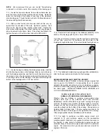
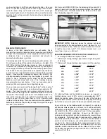
1) Remove the landing gear fairing from the bottom of the
fuselage by unscrewing the two metal screws that are holding it in
place. The screws accessible through the two access holes in the
fairing. Set the fairing aside.
❑
2) Mount the formed aluminum main landing gear in place on
the fuselage using the four M4 x 15mm PWA bolts and M4 lock
nuts provided.
When finished, screw the landing gear fairing back in place.
contact so that you have a plastic fairing-to-wood joint. Be very
careful not to cut into the balsa wood wing sheeting while you are
cutting away the covering material! When ready, permanently glue
the plastic wing fairing onto the bottom of the wing with thick CA
glue or epoxy.
❑
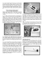
17) Plug a standard Y-harness chord into the "aileron" slot in
your receiver.
Plug the ends of your aileron servo extensions
coming out of the wing into the dual ends of the Y-harness chord.
Connect the airborne battery pack and switch harness to your
receiver and then turn on your transmitter. You should now be able
to operate your aileron servos. Perform the following setups:
a) Center the aileron servos using the transmitter trims
and/or the radio's computer options.
b) Position the servo output arms on the output shaft to
exactly 90
O
upright when the servos are neutral.
c) Test the action of the servos, making sure the output arms
move freely and that they move in the correct directions for
left and right aileron action.
d) Turn off the radio system and disconnect the aileron
servos from the Y-harness.
❑
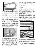
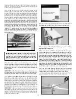
18) Locate one left and one right metal control horn and eight
M2.6 x 10mm Metal Screws.
a. Tape the ailerons in neutral position and lay the wing upside
down on your bench.
b. Position one of the control horns in place on the bottom
leading edge of the appropriate aileron. Be sure to line up the arm
of the control horn with the servo output arm. Also make sure that
the holes in the control horn are directly over the hinge line. Then
mark the control horn's 4 mounting hole locations onto the aileron
with a fine-point marker pen.
c. Drill a 3/64” dia. (or #56 drill) pilot hole into the aileron at each
mark. Mount the control horn in place, using the M2.6 x 10mm
Metal Screws. Repeat this process to attach a control horn to the
other aileron.
❑
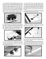
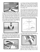
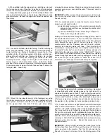
19) Locate two 4-40 x 4" threaded pushrods for the ailerons,
two 4-40 solder links, two 4-40 hex nuts, and two 4-40 threaded
R/C links. Use a soldering iron (or torch) and resin core solder
to attach a solder link onto the unthreaded end of one of the
threaded pushrods. Thread a 4-40 hex nut onto the threaded end
of the pushrod, followed by a 4-40 threaded R/C link. Connect the
solder link end of the pushrod to the aileron servo output arm
IMPORTANT: After you finish mounting the control horns on
the ailerons for the first time, take them back off and set them
aside temporarily. Then put a few drops of Thin CA into each
of the screw holes in the aileron. The Thin CA will soak into
the threads in the wood, and when it dries the holding power
of the threads will be much stronger. Use Thin CA only, not
medium or thick CA. Let the Thin CA dry completely before
remounting the control horns onto the ailerons.
Summary of Contents for SUKHOI SU-31 ARF
Page 23: ...23 ...