SIG SUKHOI SU-31 ARF Assembly Manual Download Page 12

12

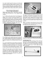
tank and the carburetor. It allows you to pump in fuel without 
having to remove the carb line from the engine. We use and 
recommend the Du-Bro #334 GLOW Kwik-Fill Fueling Valve, and
the Du-Bro #335 GAS Kwik-Fill Fueling Valve. Locate the fueling
valve in a position where it is easily accesible from outside the
cowling.

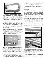
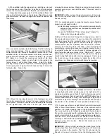
3) Fit the 1/8" x 3-1/2" x 7-1/2" plywood front fuselage hatch

onto the nose of the airplane. Simply set the hatch in place and
drill a 3/64" (or #56)  dia. hole through each corner of the hatch
and on through the plywood corner tabs mounted in the fuselage.
Take the hatch off and open up the holes in the hatch to 7/64"
diameter. Screw the hatch in place with the M2.6 X 10mm PWA
screws provided. Trim or sand any overhanging edges of the hatch
flush with the fuselage.

ADDITIONAL FUEL PROOFING: It's a good idea to paint the
hatch, firewall, and bare wood areas of the nose with a fuel-proof
paint such as clear dope, epoxy, enamel, or similar. A light coat of
fuel-proofer has been applied at the factory, but another coat will
increase the life of the model and treat the newly exposed areas
that you have drilled and/or cut out.

MOUNTING THE  COWLING

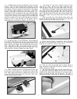
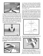
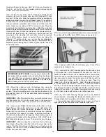
1) Before mounting the cowling, carefully inspect its inside

rear edges. Use sandpaper to smooth the inside rear surface of
the cowl, making it free of any bumps or ragged edges that may
scratch or dent the fuselage when pressed in place. Also make
sure the four mounting holes in the sides of the cowl are open and
free of any debris.

2) Slide the fiberglass cowling over the engine and back onto

the fuselage. Watch carefully to see if the cowling is going to clear
your engine installation. Continue sliding the cowling back onto
the fuselage until the engine's prop drive washer clears the front
of the cowling by at least 1/16" (1/16" to 1/8" is OK). When you've
got the position of the cowl right, use masking tape to secure the
back edge of the cowling firmly to the fuselage. Leave the four 
pre-drilled mounting holes along the back edge of the cowling
uncovered for the next step.

NOTE: The SUKHOI has lots of room inside the cowling, and the
engines that we have used fit completely inside - except for the
muffler pipes and the spark plug of the FPE 2.4 gas engine.

3) With the cowl securely taped in place, use a 3/64" (or #56)

dia. bit to drill pilot holes in the fuselage, centered in each of the
four pre-drilled holes in the cowl.

Mount the cowling to the 

fuselage with four M2.6 x 10mm PWA screws. Double check your
work one more time to make sure that the cowl is bolted on in the
correct location and alignment. Then remove the cowling from the
fuselage.

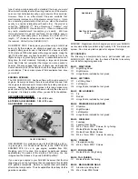
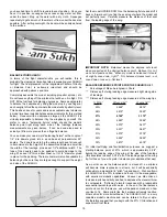
1) Assemble the fuel tank as shown. Be sure to label the

"vent" and "carb" lines for later identification.

2) Working through the wing opening in the fuselage, slide the

tank into the contoured hole in the front fuselage former. Slide it
forward until the front of the tank is approx. 1" back from the 
firewall. This will allow room for your fuel line tubing to be curved
behind the firewall over to the carb side of the engine. Drill a 5/16"
dia. hole in the firewall for the fuel feed tubing to pass through. Drill
a 5/16" dia. hole in the tank compartment floor that will let the fuel
tank vent tubing exit the bottom of the airplane. Be sure that you
don't have any kinks in the fuel line tubes that could restrict the fuel
flow. To keep the tank from moving in flight, run a bead of silicone
seal around the tank body where it contacts the fuselage former.
Another glob of silicone seal at the front of the tank secures it to
the plywood tank floor. If the tank ever has to be removed for 
service, you can cut the silicone loose and get the tank out.

NOTE: Now is the time to think about how you are going to fuel
and de-fuel your airplane. With the fuel tank assembled as shown
in the earlier steps, with one carb tube and one vent tube, you will
need to pump fuel into the carb line until it runs out the vent line.
When fuel runs out the vent line, the tank is full. With the cowling
on, it's going to be nearly impossible to reach the lines for fueling.
In this situation, we like to use a remote "fueling valve" (not 
supplied). The fueling valve goes in the carb line, between the 

Summary of Contents for SUKHOI SU-31 ARF

Page 1: ...elevator servos will be mounted on opposite sides of the fuselage in exact mirror image to each other i e with the pushrods coming off the top of each servo in direct line with the control horns This is done so the geometry of the servos pushrods and horns is exactly symmetrical on both sides providing the exact same response to control inputs for each elevator This is very important in an all out...

Page 2: ... authority than the small er engines It is simply a matter of how you want to fly the airplane RECOMMENDED ENGINES 2 STROKE GLOW ENGINES 1 50 2 10 cu in 4 STROKE GLOW ENGINES 1 80 2 70 cu in GAS ENGINES 2 4 cu in GLOW ENGINES GAS ENGINES Our preferred engine for the SUKHOI is a 2 4 cu in gas engine Our hands down favorite is the FIRST PLACE ENGINES FPE 2 4 cu in gas engine available from SIG Weigh...

Page 3: ...er climate you may notice that some wrinkles might develop after removing the covered parts from their plastic bags If that is the case there is no need to be alarmed The covering is not defective This is perfectly normal and has nothing to do with the covering material or how it was applied It has to do with the wood beneath the covering Wood takes on or loses ambient humidity Your SUKHOI ARF was...

Page 4: ...ool with Selection of Sanding and Grinding Bits Soldering Iron and Solder Large Fuel Tubing WING ASSEMBLY Before starting actual construction trial fit both wing panels onto the Hardwood Wing Joiner and the Aluminum Tube Rear Wing Joiner Check to see that the wing panels fit together in proper alignment and that both root ribs come into firm straight contact with each other If the Hardwood Wing Jo...

Page 5: ... and to check servo travel Make sure both servo output arms are 90O to the servos and that they are long enough to clear the wing s bottom surface during extremes of travel a Now attach 12 long servo extension chords to both aileron servos Note Be sure to put a piece of tape around the connecting plugs so they can t come apart while hidden in the wing b Feed the servo extension chords into the win...

Page 6: ...F 1 show the exact locations Drill completely through the foremost wing structure including the hardwood wing joiner that the hinge can be pushed in far enough for the pivot point to line up with the front V point of the aileron leading edge We recommend enlarging the opening of the hinge holes slightly with a hand held 1 4 dia drill bit You only need to twist the drill bit in about an 1 4 or so C...

Page 7: ...m of the wing where the side flanges make 11 Use slow drying epoxy to install the two hardwood dowels into the front of the wing First trial fit the dowels into the holes without glue to make sure they can be pushed in far enough You want to end up with about 1 2 of dowel remaining exposed in front of the plywood former Take the dowels back out and apply plenty of epoxy glue inside the two holes S...

Page 8: ...e servo output arms on the output shaft to exactly 90O upright when the servos are neutral c Test the action of the servos making sure the output arms move freely and that they move in the correct directions for left and right aileron action d Turn off the radio system and disconnect the aileron servos from the Y harness 18 Locate one left and one right metal control horn and eight M2 6 x 10mm Met...

Page 9: ...er engine installations will be similar 1 You need to purchase a suitable engine mount not supplied to fit your particular engine and the appropriate mounting bolts blind nuts not supplied to attach the mount to the firewall A wide variety of after market engine mounts are available Many of them are one piece and sized to fit a particular engine We recommend that you choose aluminum mounts for eng...

Page 10: ...he front of the firewall carefully aligning it with the horizontal and vertical thrust lines Mark the mount s bolt hole locations on the firewall with a pencil Drill holes completely through the firewall at those locations for the mounting bolts Finally bolt the engine mounts in place being sure to glue the blind nuts into the back of the firewall 3 With the engine mount bolted on the firewall pla...

Page 11: ...2 CYCLE GASOLINE ENGINES Gasoline engines like the FPE 2 4 pictured here fit best in the SUKHOI when mounted inverted You will need to purchase mounting bolts and blind nuts to fit your particular engine installation 1 The FPE 2 4 gas engine measures 5 from the prop drive washer to the back of the engine mount while the SUKHOI is designed with a firewall to prop washer distance of 6 Consequently y...

Page 12: ...back edge of the cowling uncovered for the next step NOTE The SUKHOI has lots of room inside the cowling and the engines that we have used fit completely inside except for the muffler pipes and the spark plug of the FPE 2 4 gas engine 3 With the cowl securely taped in place use a 3 64 or 56 dia bit to drill pilot holes in the fuselage centered in each of the four pre drilled holes in the cowl Moun...

Page 13: ... the bottom of the SUKHOI cowling to allow engine cooling air to properly flow through and exit the cowl Cooling a fully cowled engine is not difficult although many modelers have trouble doing it It s relatively simple if you follow one basic rule Simply stated the total square inches of area you have for air exit must be equal to or slightly more than the square inches of area you have in the fr...

Page 14: ... fin Let dry 8 Trial fit the fin in place on the fuselage The bottom of the fin should rest on the high point of the stabilizer a View and measure the alignment of the stabilizer to the entire airplane from several different angles Make sure that the fin is absolutely 90O upright on the fuselage and that it is aligned straight with the centerline of the fuselage not turned left or right 3 Next bol...

Page 15: ...n and eight M2 6 x 10mm Metal Screws Hold one of the control horns in position on the bottom leading edge of the appropriate elevator The horn should be as far forward as possible so that the holes in the horn line up directly over the stab elevator hinge line Also be sure the control horn lines up with the elevator servo output arm Mark the horn s hole locations on the elevator with a fine point ...

Page 16: ...eutral position Attach the solder link ends of the elevator pushrods to the servo output arms Adjust the threaded R C links to fit into the middle hole of each elevator horn Remove the tape holding the elevators in neutral and test the movement of the elevators with your radio Adjust as required to get both elevators exactly at neutral if you are using the Miracle Y splitter chord you can turn the...

Page 17: ...f masking tape hold the clear canopy tight against the base and fuselage while the glue dries b With the rudder and tailwheel both in neutral position apply a small amount of tension to the spring and use the pliers to make a 90O bend at the tailwheel steering arm hole Insert the wire into the steering arm and make another 90O bend back toward the center of the spring forming a loop Do the same fo...

Page 18: ...ed to its characteristics you will likely change the control throws to suit your style of flying But you have to start somewhere and this is where you begin These movements provide the SUKHOI with very smooth control inputs without the immediate need for exponential We suggest starting out with these movements as your low and high rates You can easily play with more control throw after you become ...

Page 19: ...ur style We therefore suggest that you begin with the 27 CG location and experiment from there you have had time to shift it around into exact position Once you have it in position squeegee the excess soapy water out from under the decal Mop up the water with a dry cloth Squeegee repeatedly to get as much of the water out from under the decal as possible After setting overnight the decal will be s...

Page 20: ...ing the model this imbalance can cause the model to pull to the heavy side especially in loops and up line maneuvers To make the airplane track true the light wing panel needs weight at the tip to balance it level with the other panel Again this can be done with stick on weights which could later be hidden inside the wingtip If you need to move your balance point fore or aft slightly the first met...

Page 21: ...nput You will also discover that your SUKHOI has outstanding inverted flight characteristics Our prototypes require only the smallest amount of down elevator to maintain level inverted flight Assuming you re comfortable and getting used to the airplane take it to a safe altitude and throttle back to get a feel for the slow flight and stall characteristics Properly balanced and trimmed your SUKHOI ...

Page 22: ...22 SUKHOI SU 31 LOG BOOK Engine Prop Flying Weight Wing Loading Balance Point Aileron Travel Elevator Travel Rudder Travel Date of first flight ...

Page 23: ...23 ...

Page 24: ...ing the most power at a reasonable cost First Place Engines are your best choice for large gasoline powered model airplane power plants All engines use piston and cylinder assemblies from world renowned manufacturers such as Husqvarna and Sachs Makita insuring long life and easy operation Using state of the art CNC machines First Place produces all other major components from high quality billet a...

Page 25: ... either model size or full size are not toys Because of the speeds that airplanes must achieve in order to fly they are capable of causing serious bodily harm and property damage if they crash IT IS YOUR RESPONSIBILITY AND YOURS ALONE to assemble this model airplane correctly according to the plans and instructions to ground test the finished model before each flight to make sure it is completely ...

Page 26: ...The color and markings of this ARF kit do not duplicate one particular full scale Sukhoi SU 31 Rather they are a realistic selection of markings typically seen on many full scale aerobatic airplanes 26 ...

Reviews: