


11
❑
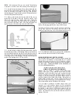
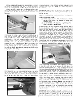
4) The throttle pushrod is a standard 2-56 size steel R/C rod
(not supplied). On the threaded end of the pushrod we used a
Du-Bro #367 Swivel Ball Link (not supplied) to connect to the
carb's throttle arm. At the servo end of the pushrod we used the
brass pushrod connector assembly that is provided in this kit.
Assemble it to the servo arm as shown in the drawing. Plug the
throttle servo into your radio system and test the action of the
throttle setup, checking for proper movement. Make sure there is
no binding.
NOTE: The carburetors on gas engines are notorious for having
a short amount of "travel", requiring limited servo movement. You
will probably find it best to mount the brass pushrod connector in
the innermost hole of the throttle servo arm.
❑
5) Drill a small hole in the fuselage former right in back of the
throttle servo to pass the servo chord into the radio compartment.
FUEL TANK AND HATCH
VERY IMPORTANT! The fuel tank parts provided in this kit are
intended for use with glow engine installations. If you are using a
gas engine, you will need to substitute a gasoline compatible fuel
tank stopper (such as Du-Bro #400 Gas Stopper) and gasoline
compatible fuel tubing (such as Du-Bro #800 Tygon Fuel Tubing)
for those items supplied in this kit. The fuel tank bottle itself is
gasoline compatible.
❑
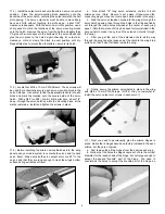
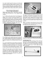
8) From the firewall, insert the bare end of the steel cable
through the nylon tube. When you get it all the way in, insert the
end of the cable into the pushrod connector on the servo. At the
other end, connect the solder link to your engine's throttle arm.
Finally cut the cable to length inside the fuselage, leaving about 1"
of extra length behind the brass pushrod connector. The extra
length will be useful when setting up the throttle travel limits later
on.
GENERAL GUIDELINES ON THE INSTALLATION OF
2-CYCLE GASOLINE ENGINES
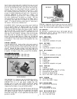
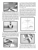
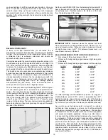
Gasoline engines like the FPE 2.4 pictured here fit best in the
SUKHOI when mounted inverted.
You will need to purchase
mounting bolts and blind nuts to fit your particular engine
installation.
❑
1) The FPE 2.4 gas engine measures 5" from the prop drive
washer to the back of the engine mount, while the SUKHOI is
designed with a firewall to prop washer distance of 6".
Consequently you will have to put a 1" thick spacer (not supplied)
between the firewall and the back of the FPE engine to achieve the
proper 6" total distance. SIG has a set of laser-cut 1/4" thick
plywood spacers specifically for the FPE 2.4.
They are part
#SIGSH802 (2 spacers per package, so you will need 2 packages
to achieve 1" total spacers). You will also need 10-32 x 1-1/2"
mounting bolts & blind nuts (not supplied).
❑
2) Position one of the plywood spacers on the front of the
firewall, carefully aligning it with the horizontal and vertical thrust
lines. Mark the mounting bolt hole locations on the firewall with a
pencil and then drill the holes completely through the firewall. Bolt
the engine and spacers onto the firewall and glue the blind nuts in
place.
❑
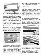
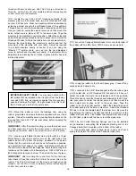
3) A pre-cut plywood servo tray is provided for mounting the
throttle servo. Decide on the best location for the tray based on
the location of your engine's throttle arm. Note that the location
and direction of movement of the throttle arm on a gas engine
varies tremendously from engine to engine. So it is not possible
for us to show you a "best" method for all gas engines. We can
only show you what worked well with the FPE gas engine we used.
With the FPE 2.4 gas engine, we found it easiest to mount the
throttle servo right behind the bottom of the firewall - see photos.
It's actually a very simple trouble-free arrangement.
Glue the
plywood servo tray in place at an angle that will provide a straight
shot from the servo arm to the carb's throttle arm. Mount the
throttle servo in the tray using the grommets and mounting screws
supplied with your radio system.
Summary of Contents for SUKHOI SU-31 ARF
Page 23: ...23 ...