


18
RADIO INSTALLATION
With all the servos now installed, all that remains is the installation
of the receiver, battery pack and switch.
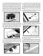
RX BATTERY PACK: The single heaviest unit of the radio system
is the battery pack. This means that you can, if needed, locate the
batteries wherever they are required in the airplane to help
achieve the correct balance point. Be sure to wrap the battery
pack in foam rubber and use rubber bands or tie-wraps to secure
it to the model structure so that it can't move around in flight.
RECEIVER: Wrap the receiver in foam and use rubber bands or
tie-wraps to secure it in the fuselage. Note that the EXTRA has an
internal receiver antenna exit tube already installed inside the
fuselage. It's the clear plastic tube running along the right side of
the fuselage, extending from the radio tray all the way back
through the fuselage, exiting just ahead of the tailwheel assembly
on the bottom. Slide your antenna into this tube when installing
your receiver.
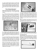
SWITCH: The switch can be mounted onto the fuselage side or
internally. We prefer an internally mounted switch. We mounted
ours onto the radio tray, using a length of music wire to activate the
switch from the outside. This is simple to do. Just drill a small
diameter hole in the switch lever to fit a piece of .045 music wire.
Drill an exit hole in the side of the fuselage, lined up with the
switch/wire location. Make a 90
O
bend in one end of the wire and
insert the short end into the hole in the switch. Apply silicone
adhesive (or double-sided foam servo mount tape) to one side of
the switch and insert the wire through the hole in the fuselage,
pressing the switch firmly to the radio tray. Make another 90
O
bend
in the wire outside of the fuselage, giving you a small "handle" to
pull and push when activating the on/off switch. Besides looking
neat, this method provides protection to the switch from dirt, debris
and exhaust.
RADIO CHECK: All servo, switch, and battery connections to the
receiver are now made. We find it easiest to leave the aileron
Y-harness plugged into the receiver aileron channel receptacle all
the time, with the two connecting ends hanging loose. Plug your
two aileron servo extension chords into the two loose ends of the
Y-harness and mount the wing to the fuselage. Turn the radio
system on and check the functions of all the controls. Make sure
they are moving in the right direction! Thousands of R/C airplanes
have crashed over the years because the servos were moving
the wrong way! Also make sure all the servos are centered and
working perfectly, without any binding. Correct any such problems
now. With everything checked and working, now is the time to set
the initial control movements.
CONTROL MOVEMENTS
This is an important section of this manual.
After flying your
SUKHOI for awhile, getting used to its characteristics, you will
likely change the control throws to suit your style of flying. But you
have to start somewhere and this is where you begin. These
movements provide the SUKHOI with very smooth control inputs
without the immediate need for exponential. We suggest starting
out with these movements as your low and high rates. You can
easily play with more control throw after you become comfortable
with the airplane, especially for 3-D type flying.
SURFACE
SUGGESTED THROWS
AILERONS:
LOWRATE:
7/8" UP
- 7/8" DOWN
HIGH RATE: 1-1/8" UP - 1-1/8" DOWN
ELEVATORS: LOW RATE: 1" UP
- 1" DOWN
HIGH RATE: 1-1/2" UP - 1-1/2" DOWN
RUDDER:
2-1/4" RIGHT - 2-1/4" LEFT
Remember:
Control surface movements should always be
measured at the widest point of the control surface.
SAFETY ISSUE: After centering all the servos and setting the
control surface throws, make sure each R/C link has a short length
of fuel tubing in place to prevent it from coming disconnected from
either the control horns or the servo output arms. Also be sure
you have tightened each of the 4-40 hex nuts tightly against all
threaded R/C links, locking them in place.
DECAL APPLICATION
The decals provided with this kit are typical of the markings that
might be seen on full-scale SUKHOI. They are not intended to be
a complete set of markings to duplicate one particular SUKHOI
SU-31. However, I think you'll agree that when applied to the
airplane as shown on the box label, they look very realistic and
believable. Feel free to use all or only some of the decals in
different locations as you see fit.
The decals are made of adhesive-backed mylar, they are NOT
water activated transfers. These decals are not die-cut and need
to be cut from their sheets with a sharp #11 blade or good pair of
scissors. Trim as close to the image as possible.
Putting sticky-back decals on a model can be tricky! Especially
medium to large size ones like those in this kit. If you don't do it
right you will end up with unsightly air bubbles trapped underneath
the decal. Here's a method that eliminates that problem entirely
and makes the job easy and fun.
You will need a "soapy water" mixture (water mixed with a very
small amount of dish soap, or SIG Pure Magic Model Airplane
Cleaner, or Fantastic
®
, Windex
®
, or 409
®
type cleaners all work
good). You will also need a supple squeegee (the SIG 4" Epoxy
Spreader #SIGSH678 is perfect for this job), a couple clean soft
cloths (old tee shirts are great), a good straight edge, a ruler, and
a hobby knife with sharp #11 blades. We also suggest that you
have some trim tape handy for making temporary guidelines (1/8"
width or so is perfect) for help in aligning the decals.
First spray the surface of the model where the decal is to be
placed with a soapy water mixture. Then peel the backing sheet
completely off the decal, being careful not to let the sticky side
double over and adhere to itself. Place the decal onto the wet
surface of the model.
Do not push down! The soapy water
solution will keep the decal from actually sticking to the model until
Summary of Contents for SUKHOI SU-31 ARF
Page 23: ...23 ...