


16
❑
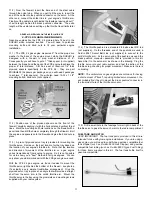
17) Mount the T-shaped Metal Rudder Horn onto the bottom of
the rudder with two M2 x 9mm PWA Screws, as shown here.
❑
18) Hinge the rudder to the fin with epoxy glue. Clean off any
excess glue and allow to dry.
❑
19) Locate a 4-40 x 4-5/8" threaded pushrod for the rudder, plus
a 4-40 solder link, a 4-40 threaded R/C link and a 4-40 hex nut.
Solder the solder link onto the unthreaded end of the pushrod.
Thread the hex nut onto the threaded end, followed by the R/C link.
Use your radio to center the rudder servo and then mount the
servo output arm in place at 90° to the servo body. Tape the
rudder to the fin in neutral position. Attach the solder link end of
the rudder pushrod to the servo output arm. Adjust the threaded
R/C link to fit into the middle hole of the rudder horn. Remove the
tape holding the rudder in neutral and test the movement of the
rudder with your radio. Final rudder throw adjustment and locking
the R/C links in place with the hex nuts will be made later.
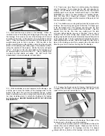
❑
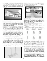
20) The two Coiled Steering Springs can now be installed
on the tailwheel, connecting the tailwheel's steering arm to the
T-shaped metal horn mounted on the bottom of the rudder.
a. Use needle nose pliers to bend loops in one end of each
spring to hook into the holes of the T-shaped rudder horn.
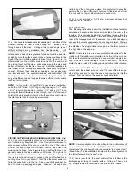
threads will be much stronger. Use Thin CA only, not medium or
thick CA. Let the Thin CA dry completely before remounting the
control horns onto the elevators.
❑
14) Locate the two 4-40 x 2-3/4" threaded pushrods for the
elevator, plus two 4-40 solder links, two 4-40 threaded R/C links
and two 4-40 hex nuts. Make two elevator pushrod assemblies by
soldering a solder link onto the unthreaded ends of the pushrods.
Thread a hex nut onto the threaded ends, followed by an R/C link.
Use your radio to center the elevator servos and then mount the
servo output arms in place at 90° to the servo body. Tape the
elevators to the stabilizer in neutral position. Attach the solder link
ends of the elevator pushrods to the servo output arms. Adjust the
threaded R/C links to fit into the middle hole of each elevator horn.
Remove the tape holding the elevators in neutral and test the
movement of the elevators with your radio. Adjust as required
to get both elevators exactly at neutral (if you are using the
"Miracle Y™" splitter chord, you can turn the pot adjustment
screw to achieve exact neutral very easily). Final elevator throw
adjustments and locking the R/C links in place with the hex nuts
will be made later.
❑
15) Mount the rudder servo in the fuselage now, using the
rubber grommets and screws that were supplied with your radio
system. It's best to mark the servo mounting hole locations on the
plywood first, then drill 1/16" dia. pilot holes, before screwing the
servo in place.
IMPORTANT: After the initial mounting, remove the rudder servo
and flow some thin CA into the screw holes in the plywood to
toughen up the holes. When dry, screw the servo back in place.
❑
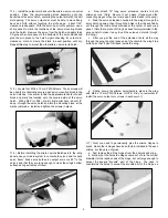
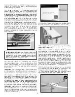
16) Locate one left Metal Control Horn and four M2.6 x 10mm
Metal Screws. Mount the control horn on the right side of the
rudder, about 3/8” up from the bottom, as shown in the photos.
Notice that the control horn should be as far forward as possible,
up against the front edge of the rudder, so that the pivot holes in
the control horn line up with the hinge line. Mark the mounting hole
locations on the rudder with a fine-point pen. Drill a 3/64” dia. (or
#56 drill) pilot hole for each screw. Then screw the horn in place.
IMPORTANT: After mounting the control horn for the first time,
take it back off and flow some thin CA into the screw holes in the
rudder. The Thin CA will soak into the wood and toughen up the
threads. Let the Thin CA dry completely before remounting the
control horn onto the rudder.
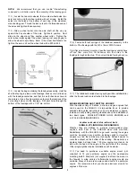
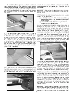
IMPORTANT SAFETY ISSUE: You may have noticed in the
last picture that we installed a short length of fuel line tubing
over each R/C link, as insurance against the link popping
open and coming off in flight. It’s a good idea to do this to all
the R/C links you use in all of your models.
Summary of Contents for SUKHOI SU-31 ARF
Page 23: ...23 ...