


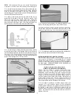


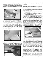


Drill a 9/64" dia. hole through the firewall, aligned with your
engine's carburetor throttle arm. From the front, insert the 1/8"
nylon pushrod tube through the firewall and into the fuselage,
leaving about 3" of tube exposed in front of the firewall (typical
when using a 1.20 or 1.50 2-stroke engine). With the tube in place,
turn the fuselage over and note the location of the tube in
relationship to the throttle servo. You want to position the tube
directly in front of the servo's output arm.
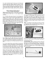
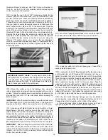
Slip the plywood
throttle pushrod support over the end of the tube.
Glue the
support to the former in the location that will aim the nylon tube
directly at the throttle servo output arm. Then use a sharp razor
blade to cut the nylon tube to length 1" beyond the plywood tube
support.
Remove the tube and sand its surface with 220
sandpaper to rough it a little. Reinstall the tube and glue it in place
to the firewall and the plywood tube support with thick CA glue.
❑
6) Solder the 2-56 solder link to one end of the steel cable -
this is the carburetor end of the throttle pushrod. In addition to
attaching the solder link to the end of the cable, you should flow
some solder into the last 1" to 2" of cable (depending on your
specific installation) to stiffen it. Also flow solder into the last 1" of
the other end of the cable to stiffen it and keep it from unraveling.
❑
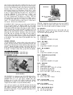
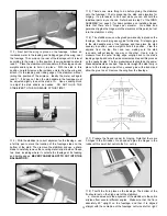
7) Install the brass
pushrod connector
assembly to the output
arm on the throttle
servo, as shown in the
drawing.
❑
2) Horizontal and vertical engine thrust line marks are scribed
onto the front of the firewall. Use a straightedge and pencil to
extend the lines all the way to the edges of the firewall. Position
your engine mount on the front of the firewall, carefully aligning it
with the horizontal and vertical thrust lines. Mark the mount's bolt
hole locations on the firewall with a pencil. Drill holes completely
through the firewall at those locations for the mounting bolts.
Finally, bolt the engine mounts in place, being sure to glue the
blind nuts into the back of the firewall.
❑
3) With the engine mount bolted on the firewall, place your
engine on the mount. Move the engine forward or backward on the
mount until you measure exactly 6" from the front face of the prop
drive washer to the front of the firewall. This is the distance your
engine needs to be from the firewall for proper cowl mounting and
prop clearance purposes. Mark your engine's mounting bolt hole
locations onto the engine mounts and remove the engine. Drill the
required holes in the engine mounts, and then bolt the engine in
place with suitable mounting bolts (not supplied).
❑
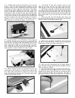
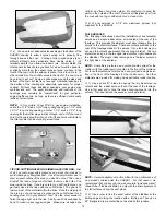
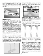
4) A pre-cut plywood servo tray is provided for mounting the
throttle servo. Decide on the best location for the tray based on
the location of your engine's throttle arm. In most cases, with a
single-cylinder engine, the best location will be on the right side of
the fuselage, just behind the front fuse former - see photo. Glue
the servo tray securely in place, and then mount the throttle servo
in the tray using the grommets and mounting screws supplied with
your radio system.
It's best to mark the servo mounting hole
locations on the plywood first, then drill 1/16" dia. pilot holes,
before screwing the servo in place.
❑
5) Next we're going to assemble the throttle pushrod. Locate
the 1/8" od x 18" nylon pushrod tubing, the 1/16" x 18" stranded
steel cable, the pre-cut 1/8" plywood throttle tube support (has one
rounded end with a hole for the tube), the pushrod connector
assembly (hex brass body, nylon retainer and 4-40 x 1/8" socket-
head cap screw), and the 2-56 solder link.
10
Summary of Contents for SUKHOI SU-31 ARF
Page 23: ...23 ...