28
INSTALLATION & OPERATION
2
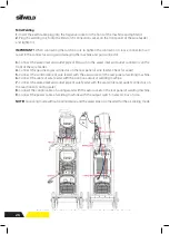
(14) Select the desired MIG function, Select program number to suit the wire diameter
and gas type being used as shown on the display.
(15) Select torch switch mode: 2T/ 4T/ S4T/ Spot weld.
(16) Set the required welding parameters to suit the material thickness being welded.
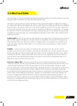
§4.3.2 Wire Feed Roller Selection
The importance of smooth consistent wire feeding during MIG welding cannot be
emphasized enough. Simply put the smoother the wire feed then the better the weld.
Feed rollers or drive rollers are used to feed the wire mechanically through the length of
the welding gun cable. Feed rollers are designed to be used for certain types of welding
wire and they have different types of grooves machined in them to accommodate the
different types of wire. The wire is held in the groove by the top roller of the wire drive unit
and is referred to as the pressure roller, pressure is applied by a tension arm that can be
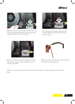
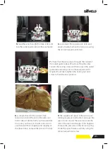
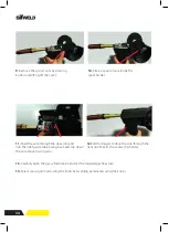
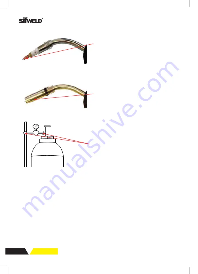
(13) Carefully open the gas cylinder valve and
set the required gas flow rate.
(12) Fit the gas nozzle to the torch head.
(11) Fit the correct sized contact tip and feed
the wire through it, screw the contact tip into
the tip holder of the torch head and nip it up
tightly.
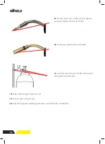
15.
Fit the correct size contact tip over the wire
and fasten tightly into the tip holder.
16.
Fit the gas nozzle to the torch head.
17.
Carefully open the gas cylinder valve and set
the required gas flow rate.
18.
Select torch trigger mode: 2t or 4T.
19
. Select water cooling mode..
20
. Select the required welding parameters using the knobs and buttons.
Summary of Contents for Evolution MTS400 SYN
Page 39: ...39 Notes ...


