25
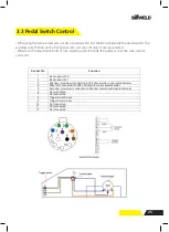
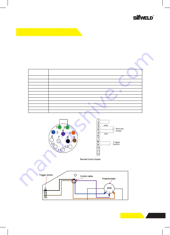
3.3 Pedal Switch Control
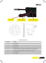
DIAGRAM FOR GUN
21
Pedal switch control
● When plug the twelve
-lead aero-socket of pedal switch in it. Welder will identify the
pedal switch, the welding current knob on the front panel will can’t use
,
and only 2T can
be selected.
●
When use the adjustment knob of max-welding current beside the pedal, can set the
max-current you want.
Socket Pin
Function
1
Be shorted with 2
2
Be shorted with 1
3
20k ohm (maximum) connection to 20k ohm remote control potentiometer
4
Wiper arm connection to 20k ohm remote control potentiometer
5
Zero ohm (minimum) connection to 20k ohm remote control potentiometer
6
Not connected
7
Not connected
8
Trigger Switch Input
9
Trigger Switch Input
10
Not connected
11
Not connected
12
Not connected
• When plug the twelve-lead aero-socket of pedal switch in it. Welder will identify the pedal switch, the
welding current knob on the front panel will can’t use and only 2T can be selected.
• When use the adjustment knob of max-welding current beside the pedal, can set the max-current
you want.
Summary of Contents for Evolution MTS400 SYN
Page 39: ...39 Notes ...


