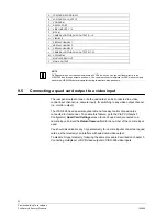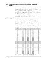
44
Siemens Building Technologies
Fire Safety & Security Products
10.2008
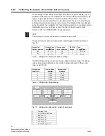
9.6.7
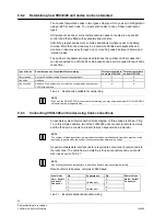
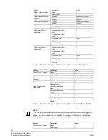
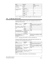
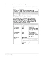
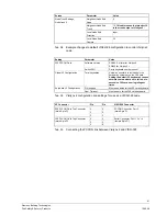
Controlling 64 cameras x 64 monitors (full cross point)
A second bridge mode, bridge mode B, provides full cross point switching. Up to a
maximum of 64 cameras are available with the restriction that coaxial telemetry (C
Type) is only available when cameras are switched to monitors 1 to 16. The
camera inputs are connected from one ‘monitor node’to the next via loop-through
cables, giving all monitors access to all cameras. The filtering on the loop-through
connections limits the availability of C Type telemetry and also some camera signal
degradation may occur as it passes down the chain of loop-through circuits.
Camera control over RS422/RS485 is fully supported.
NOTE
Alarm handling and multi-hop networking are not supported in bridge mode B
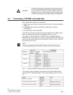
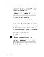
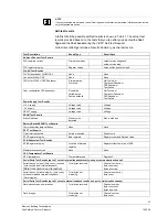
The special network address mode used to select bridge mode B is detailed in
Tab. 34.
Bridge Unit
Network Address
‘Monitor Node’
Cams
×
Mons
‘Monitor Node’
Network Address
VIS3I-328
Needed
Total
Cams
×
Mons
B0
32
×
16
00 5
32
×
64
B1
64
×
16
00 9
64
×
64
Tab. 34
Bridge mode B network address settings
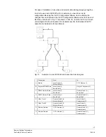
The PCCON networking connections are as bridge mode A and again the bridge
node serial port used determines the monitor numbers allocated to the monitor
node, as per Tab. 35.
Bridge Node
Serial Port
‘Monitor Node’
Cameras
‘Monitor Node’
Monitors
1
1 to 64
1 to 16
2
1 to 64
17 to 32
3
1 to 64
33 to 48
4
1 to 64
49 to 64
Tab. 35
Bridge mode B addressing
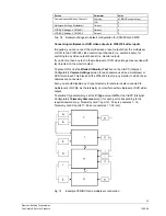
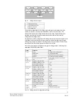
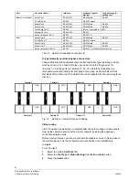
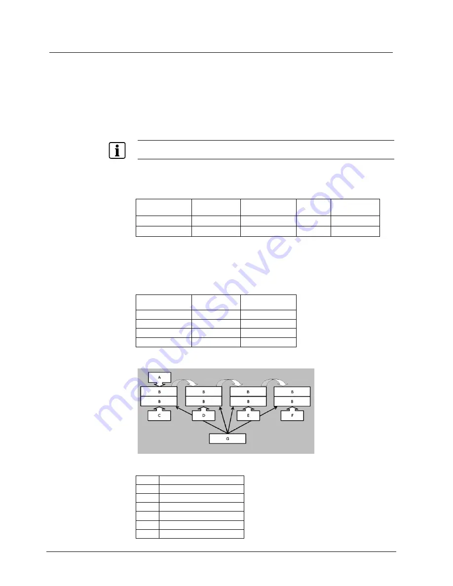
Fig. 15
Bridge mode B layout; 64 x 64 full cross point
A
Cameras 1 to 64
B
VIS3I-328 Monitor Node
C Monitors
1-16
D Monitors
17-32
E Monitors
33-48
F Monitors
49-64
G
VIS3I-328 Bridge Unit

