
52
Siemens Building Technologies
Fire Safety & Security Products
10.2008
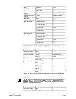
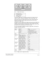
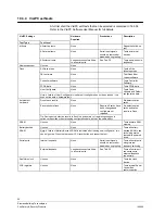
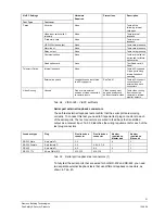
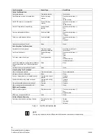
Unit
Connector Name
Interface
Loopback type for
first test
Loopback type for
second test
Serial Port 1
RS-232/422
RS-232 Male
RS-422
PCCON Port 2
RS-232
RS-232 Female
Serial Port 3
RS-232/422
RS-232 Male
RS-422
Serial Port 4
RS-232/422
RS-232 Male
RS-422
Test/Config Port 9
RS-232
(None – connected to VisiPC)
Keyboard Port 10
RS-422/485
RS-422
Master or standalone
Option card ports 12 & 13
RS-232
RS-232 TTL
Serial Port 16
RS-232/422
RS-232 Male
RS-422
PCCON Port 17
RS-232
RS-232 Female
Serial Port 18
RS-232/422
RS-232 Male
RS-422
Serial Port 19
RS-232/422
RS-232 Male
RS-422
Slave
Option cards ports 20 & 21
RS-232
RS-232 TTL (at either card connector)
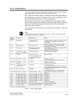
Tab. 40
Serial port loopback connectors (2)
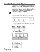
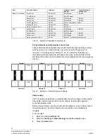
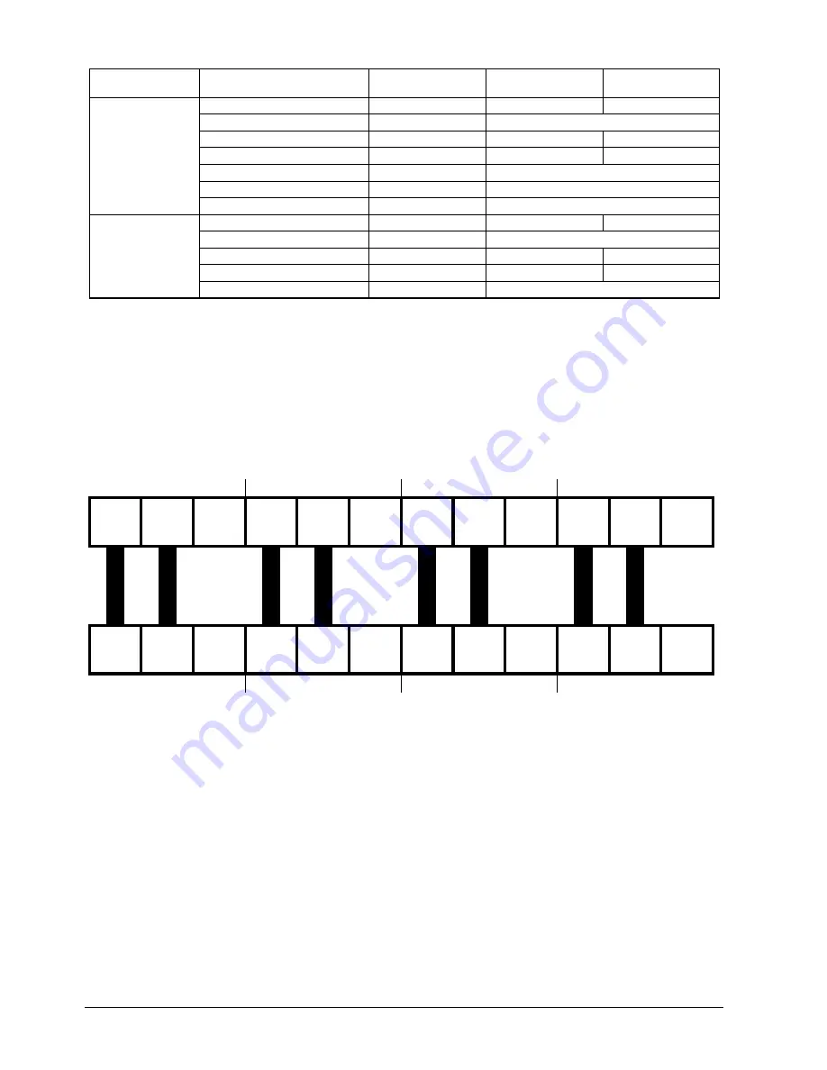
D-type telemetry external loopback connectors
These self-test external loopback tests confirm that the D-type telemetry ports are
working correctly. To conduct this test, you need to link the D-type ports for
cameras 1–16 to the ports for cameras 17–32. You do this by linking the two
removable screw terminal blocks with pairs of link wires, as shown below for the
first block of four cameras. (This pattern should be repeated for the remaining three
blocks.)
Camera 1
Camera 2
Camera 3
Camera 4
+ -
GND
+ -
GND
+ -
GND
+ -
GND
Link
Link
Link
Link
Link
Link
Link
Link
+ -
GND
+ -
GND
+ -
GND
+ -
GND
Camera 17
Camera 18
Camera 19
Camera 20
Fig. 16
Self-test – Camera D-type port linking
Video routing
VisiPC includes a powerful test to automatically check the routing of video signals
from all the camera inputs to all the monitor outputs, including the expansion
connection between units.
Before running this test, you should connect all available sources of clean video to
the camera inputs. This test is therefore best conducted once installation is
complete.
To run the test:
1.
Select the VisiPC
Self-Test
Tab.
2.
Select the
Test Type
to
Video Routing
from the
Run Tests
button.
3.
Press the
Send
button.


