23
Siemens Building Technologies
Fire Safety & Security Products
10.2008
8 Commissioning
Following installation, each VIS3I-328 should be commissioned by performing the
following tasks, in the sequence shown:
1.
Inspect all items (see chapter 8.1).
2.
Connect a PC running VisiPC software (see chapter 8.2).
3.
Set VisiPC default product to integrated (see chapter 8.3).
4.
Connect and power up the VIS3I-328(s) (see chapter 8.4).
5.
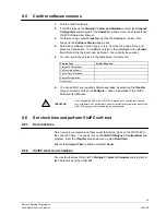
Confirm software versions – upgrade as necessary (see chapter 8.5).
6.
Set clock time and perform VisiPC self-test (see chapter 8.6).
7.
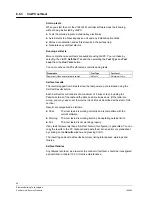
Load new configuration, as necessary (see chapter 8.7).
8.
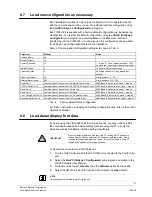
Load Asian display font data, if necessary (see chapter 8.8).
Commissioning Tasks 3 to 8 are conducted using the VisiPC Test and
Configuration software, which should be installed on a suitable PC. A full
description of the VisiPC software is contained in the User Manual.
8.1
Inspect all items
1.
Visually inspect all the units, especially all input and output connections.
2.
Check the contents of the shipping package against the packing note.
8.2
Connect a PC running VisiPC software
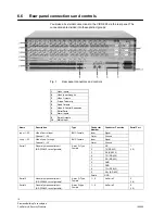
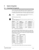
The VIS3I-328 incorporates an RS232 Test/Config connector port on the rear
panel which allows connection, via a 9-way to 9-way interface lead (Type VIS3-
CONF), to a PC for system configuration and testing using the VisiPC software.
NOTE
If the serial COM Port on the PC is a 25-way connection, then you need to purchase a suitable 9-way
to 25-way ‘D’ type pre-wired interface lead.
Tab. 4 and Tab. 5 are for reference and give details of the pin-outs used for RS232
transmission.
NOTE
The 25-way to 9-way option is wired differently to the 9-way to 9-way cable. If you are manufacturing
this lead, then you must observe these pin-outs.
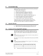
PC COM Port 9-Way ‘D’ Female
VIS3I-328 Test/Config Connector 9-Way ‘D’ Male
2 2
3 3
5 5
Tab. 4
Cable wiring for 9-way PC COM port (Part Number VIS3-CONF)

