36
Siemens Building Technologies
Fire Safety & Security Products
10.2008
9.6.2
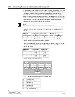
Determining how VIS3I-328 unit nodes can be networked
You connect networked nodes in two types of layout, which you set in configuration
using VisiPC at each node. You must set all nodes to one of these node layout
types:
A Star layout has one or more remote camera nodes connected to one central
control node that is fitted with keyboards and monitors.
A Multi-hop layout can be more complex and allows multiple nodes to be daisy-
chained. More than one node may be a control node fitted with keyboards and
monitors. Video may pass through one or more 'hop nodes' between camera and
‘monitor nodes’.
The number of available serial ports determines the number of other nodes that
can be connected to a VIS3I-328 node, because one port is required for each node
connection.
Type of node
Serial data ports not available for networking
Total ports available
on single VIS3I-328
Total ports available
on dual VIS3I-328
Camera node
Any Test/Config port and a Slave unit Keyboard port.
5
9
Hop node
As above.
5 9
Control node
As above. Also, at least one port must be configured as a keyboard or
PCCON control port.
4 8
Tab. 20
Serial ports available for networking
NOTE
If you use the RS-232 PCCON serial port for networking, you may need an external RS-232 to RS-422
converter to drive a long serial line.
9.6.3
Connecting VIS3I-328 unit nodes using trunk connections
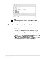
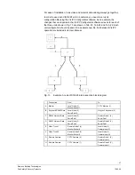
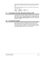
An example system interconnection block diagram of three nodes is shown in Fig.
13. In this simple example, two of the VIS3I-328 units connect to remote cameras
and the third unit connects to a local Visilynx 3 keyboard and a monitor.
NOTE
The number of video inputs from remote nodes that can be simultaneously viewed on monitors at the
local node is governed by the number of trunk connections between the nodes.
A special network data interface cable is required to connect each remote node to
the local node. The cable has two male 9-pin D-type connectors and you should
wire it as shown in Tab. 21.
NOTE
Any of serial port connectors Serial 1, Serial 3 and Serial 4 may be configured for this.
Data transfer is full-duplex, normally at 9600 baud.
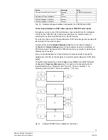
Pin Connected
to
Pin
4 5
8
(twisted pair)
9
5 4
Local Node
Unit – Serial 1
or Serial 3
Connector
9
(twisted pair)
8
Remote Node
Units – Serial 1
Connector
Tab. 21
Example network data cable wiring

